2 redundancy installation – Comtech EF Data CME-5000 Manual User Manual
Page 30
Digicast Micro Encapsulator (MENCAP)
Revision A
Installation & Initial Configuration MN/MENCAPEDC.IOM
2.3.2 Redundancy
Installation
The MENCAP 50 Redundancy (CME-5100 or CME-5110) is designed for ease of
installation and configuration. Once the unit has been removed from the packing
container, please follow these instructions:
Step
Procedure
1
Place the MENCAP Redundancy configuration into a rack. This configuration requires
a single rack unit (1RU) in a standard 19” rack enclosure.
2
Connect an RJ-45 Ethernet cable (patch cord) to the port labeled ETHERNET on the
Primary unit and Secondary unit (left and right, respectively, looking at the front).
These cables should connected to an Ethernet concentrator (hub) or switch.
3
Connect a terminal cable (supplied) to the port labeled TERM. This cable should be
connected to a PC’s serial port (DB-9) to initially configure the MENCAP 50.
4
Connect the AC power cords between a standard wall outlet and the power supply.
The Blue LEDs will illuminate on both MENCAP 50 chassis and the CME-1600
Redundancy Switch chassis.
5
IMPORTANT
It is recommend that the ASI cable NOT be connected until the
unit has been completely configured.
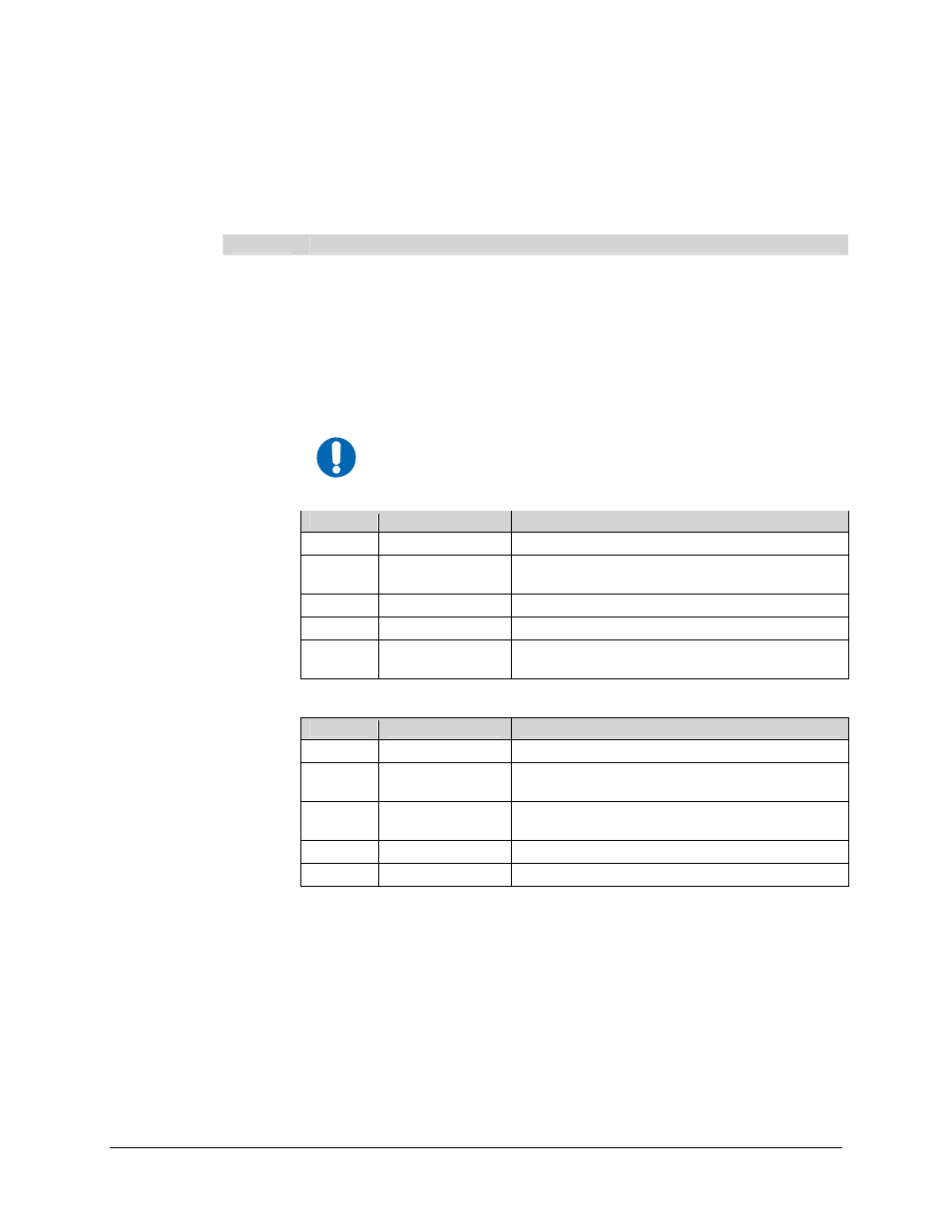
Upon startup, the following LEDs will illuminate on the MENCAP 50 front panels:
LED
Function Label
Description
Blue
POWER
LED illuminates if power is properly applied
Red
ALARM
LED may illuminate since the unit is not yet
configured
Green
M-ACT
LED illuminates if MPE data is present
Amber
E-ACT
LED flashes if there is Ethernet traffic/activity
6
Green
E-LINK
LED illuminates if Ethernet connection to the
Hub/Switch is operational
Concurrently upon startup, the following LEDs will illuminate on the CME-1600
Redundancy Switch front panel:
LED
Function Label
Description
Blue
POWER
LED illuminates if power is properly applied
Green
PRI
LED illuminates if PRIMARY unit is enabled
(default)
Green
AUTO
LED flashes if unit is in AUTO configuration
(default)
Green
SEC
LED illuminates if SECONDARY unit is enabled
7
Red
ALARM
LED should not illuminate
2-4