Demodulator, 3 demodulator, Figure 4-3. demodulator block diagram – Comtech EF Data SNM-1000 User Manual
Page 128
Advertising
SNM-1000 Node Control Modem
Revision 3
Theory of Operation
MN/SNM1000.IOM
4–10
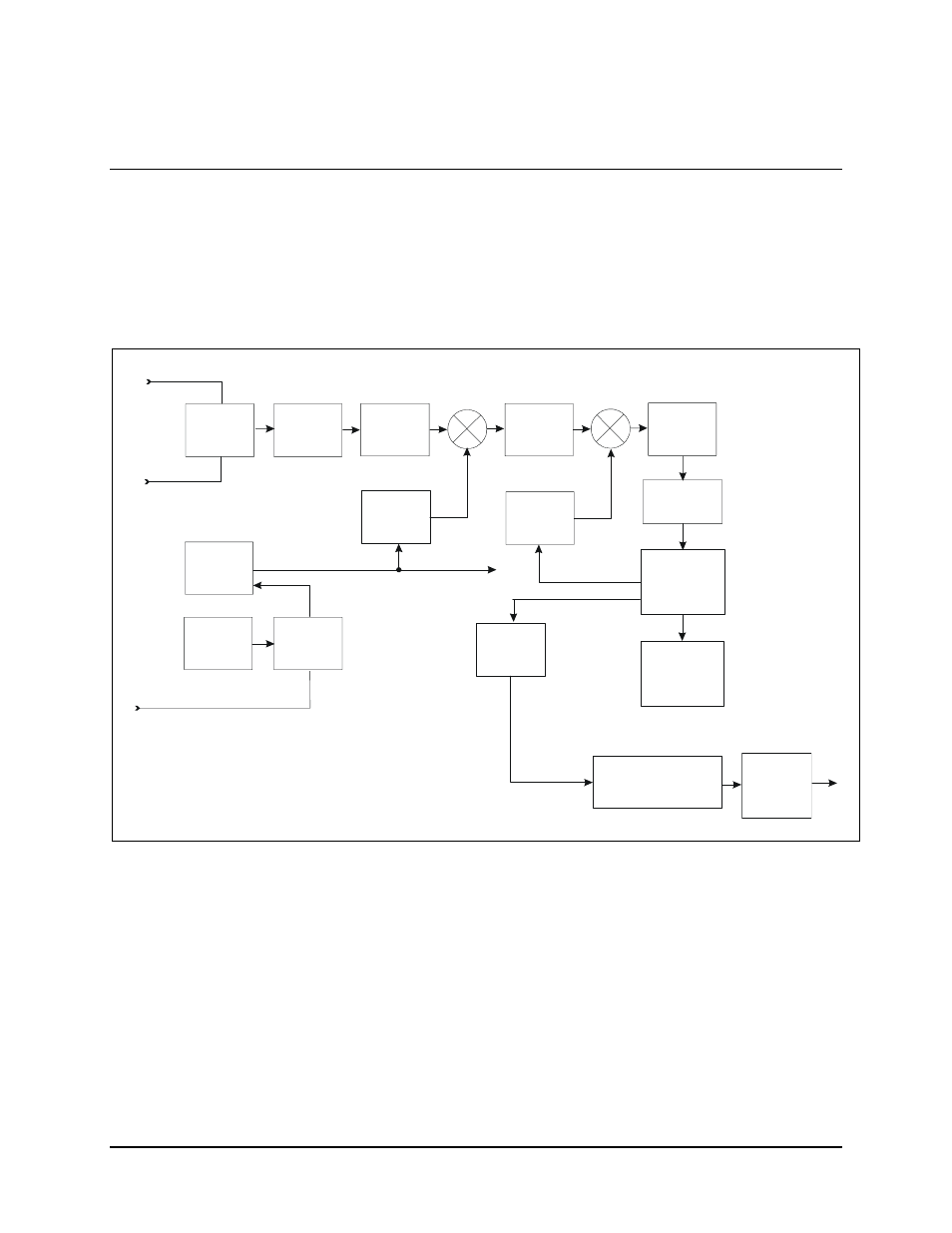
4.3 Demodulator
The demodulator converts PSK modulated carriers within the 50 to 180 MHz range to a
demodulated baseband data stream. The converted modulation type is QPSK, (refer to
Section 4.2.3 for a description of modulation type). The demodulator then performs FEC
on the data stream using the Viterbi decoding algorithm.
A block diagram of the demodulator is shown in Figure 4-3.
DIGITAL
SIGNAL
PROCESSING
DIGITAL
CLOCK
RECOVERY-
LOOP
SWITCH
REF
VCXO
REF
PLL
OC XO
OPT
HIGH
STABILITY
AGC
LPF
BPF
LO #2
LOOPBACK
RF INPUT
RF INPUT
50 TO 180 MHz
BPF
A TO D
CONVERTER
LO #1
REFERENCE
VITERBI
DECODER
DOPPLER/
PLESIOCHRONOUS
BUFFER
INTERFACE
EXT REFERENCE
Figure 4-3. Demodulator Block Diagram
Advertising