DFI SR330-N User Manual
Page 21
21
2
Hardware Installation
2. Apply a thin layer of thermal paste on top of the CPU. Do not
spread the paste all over the surface. When you later place the
heat sink on top, the compound will disperse evenly.
3. While holding the retention module base in position (step 1),
place the fan / heat sink assembly on top of the CPU. The 4
screws around the heat sink must match the screw holes of the
retention module base. We strongly recommend using this type
of fan / heat sink assembly because it provides adequate cooling
to the components of the system board.
Turn each Phillips head screw half way down first to initially stabi-
lize the heat sink onto the board, then finally tighten each screw.
Important:
Do not turn the first screw all the way down followed by
the next and so on. This is to avoid imbalance which might
cause cracks or fractures to the CPU and/or heat sink as-
sembly.
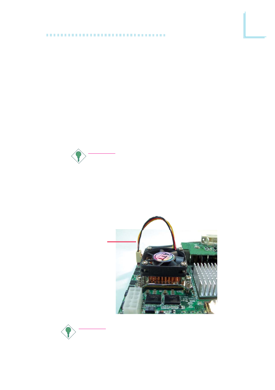
4. Connect the CPU fan’s cable connector to the CPU fan connec-
tor on the system board.
CPU fan
cable
Important:
When you install the CPU fan and heat sink assembly, make
sure the assembly is positioned in such a way that the direc-
tion of the airflow blows towards the Northbridge. This is to
ensure optimum thermal condition and system performance.