DR Power Self-Propelled 6.75 Pro-XL (September 2010 - April 2013) User Manual
Page 8
8
DR
®
TRIMMER/MOWER
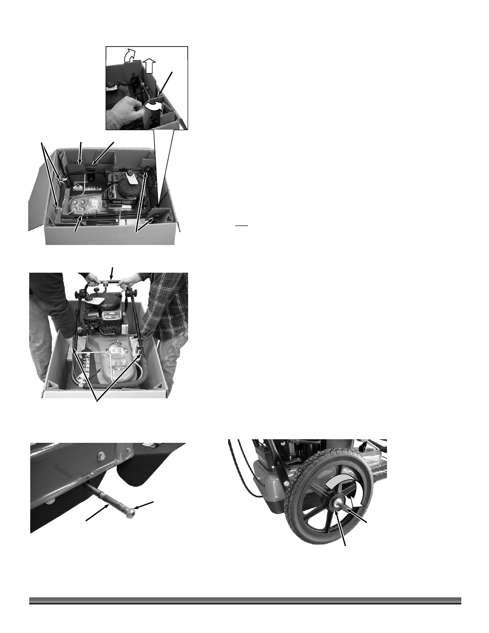
Do Not Lift on
Upper Handlebar
Figure 5
Lower Handlebar
Figure 7
Red Mark on Outside of Hub
(For Right Side Wheel)
Plastic
Insert
4. Hold the Upper Handlebar and use Wire Cutters to cut the Cable Ties that
attach the Upper Handlebar to the Box (Figure 4).
5. Remove the Wheels and Wheel Inserts from the Shipping Box.
6. Rotate the flaps out over the Hand Knobs as you pull the Hand Knob Insert
from the back of the Box.
NOTE: You will need two people to lift the Trimmer from the Box. Do not lift on
the Upper Handlebar. Lift from the Lower Handlebar and bottom of the machine.
7. With help from another person, lift the Trimmer from the Shipping Box
(Figure 5).
8. Position the Trimmer on the ground so you have access to the ends of the
Axle and remove the Locknuts from both ends of the Axle (Figure 6). They
should be loose enough to remove by hand.
NOTE: The right and left side of the machine is referenced from the Operating
position.
9. For the non self-propelled Trimmer, slide the Wheels onto the Axle with the
smooth side of the Hub facing out and go to step 12.
NOTE: On the self-propelled Trimmer the right side wheel has a red mark on the
smooth side of the Hub and will face away from the Trimmer Body. The left side
wheel has a blue mark on the smooth side of the Hub and will also face away from
the Trimmer Body.
10. For the self-propelled Trimmer, install the right side wheel onto the Axle by
rotating it clockwise as you slide it onto the Axle (Figure 7).
NOTE: A plastic plug will come out of the Wheels as you slide them on. Save this
plug to insert back into the Wheels if they need to be removed in the future.
11. Install the left side wheel onto the Axle by rotating it counter-clockwise as
you slide it onto the Axle.
12. Secure the Wheels to the Axle with the two Locknuts using a 5/8" Wrench.
You may need to hold the axle with Locking Pliers to keep it from turning
(use a rag or similar to protect the Shaft from damage).
Figure 4
Cable Ties
Handlebar
Hand Knobs
Upper
Handlebar
Hand
Knob
Insert
Wheel
Insert
Wheel
Axle (Right Side)
Figure 6
Locknut