Flowserve Mark 3 Sealed Metallic Durco User Manual
Page 23
MARK 3 USER INSTRUCTIONS ENGLISH 71569102 01-13
Page 23 of 72
flowserve.com
condition. If any is present it is eliminated by
shimming.
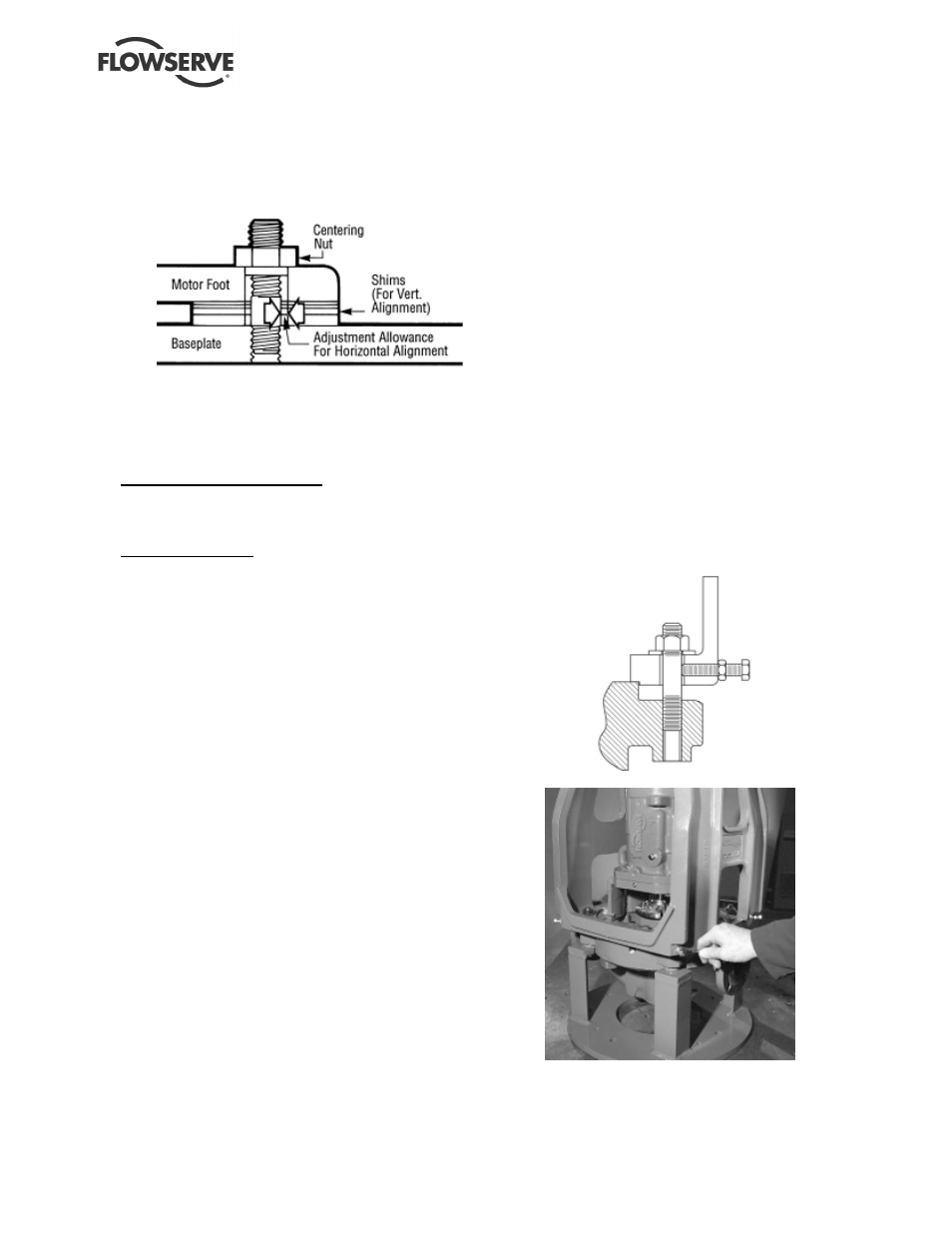
d) The motor feet holes are centered on the motor
mounting fasteners. This is done by using a
centering nut as shown in figure 4-9.
Figure 4-9
e) The motor is fastened in place by tightening the
nuts on two diagonal motor mounting studs.
f) The pump is put onto the baseplate and leveled.
The foot piece under the bearing housing is
adjustable. It is used to level the pump, if necessary.
Mark 3A and ANSI 3A design
If an adjustment is necessary, add or remove
shims [3126.1] between the foot piece and the
bearing housing.
Mark 3 design (old)
If an adjustment is necessary, the adjuster nut
[6576] is used to move the footpiece up or down.
g) The spacer coupling gap is verified.
h) The parallel and angular vertical alignment is
made by shimming under the motor.
i)
The motor feet holes are again centered on the
motor mounting studs using the centering nut. At
this point the centering nut is removed and
replaced with a standard nut. This gives
maximum potential mobility for the motor to be
horizontally moved during final, field alignment.
All four motor feet are tightened down.
j)
The pump and motor shafts are then aligned
horizontally, both parallel and angular, by moving
the pump to the fixed motor. The pump feet are
tightened down.
k) Both horizontal and vertical alignment is again
final checked as is the coupling spacer gap.
See section 4.8, Final shaft alignment.
4.5.2
In-Line initial alignment procedure
The factory alignment proceed procedure ensures
that the unit may be aligned in the field. The initial
alignment is no more than 0.38 mm (0.015 in.)
parallel, and 0.0025 mm/mm (0.0025 in./in.) angular
misalignment.
The Mark 3 In-Line incorporates motor alignment
capabilities. Parallel alignment is achieved by
moving the motor adapter and motor as an assembly
relative to the power end. Four adjustment screws
(as shown in figures 4-10 and 4-11) allow for precise
changes in parallel alignment. Angular alignment is
controlled by machining tolerances, but cannot
prevent uneven cover gasket compression.
a) Check angular alignment. Additional torque may
be applied to the appropriate casing bolts to
correct angularity.
b) Check parallel alignment within a plane defined by
the adjusters at opposite corners of the motor
adapter. To make corrections, the motor adapter
nuts [6580.3] must be slightly loosened to allow the
motor adapter to move. All adjusters except for the
one in the desired direction of motor movement
should be loosened during adjustment. Tighten the
adjuster slowly against the stud until desired
alignment numbers are reached.
c) Check parallel alignment within a plane 90
degrees from the first. Corrections are made as
described in the previous step.
d) Several iterations between planes may be
necessary. Tighten all fasteners and recheck
alignment.
Figure 4-10
Figure 4-11