Flowserve Mark 3 Sealed Metallic Durco User Manual
Page 59
MARK 3 USER INSTRUCTIONS ENGLISH 71569102 01-13
Page 59 of 72
flowserve.com
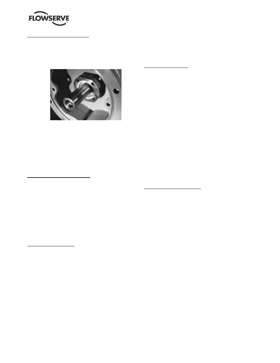
Single internal seal installation
d) Place the gland [4120] and stationary seat onto
the shaft until it lightly touches the bearing
housing (Group 1) or adapter (Group 2 and 3).
e) Install a gland gasket [4590.3] into the gland.
(See figure 6-35.)
Figure 6.34
f)
Locate the rotary seal unit onto the shaft (or sleeve)
according to the set dimension provided by the seal
manufacture. Tighten set screws on the seal to
lock the rotating unit to the shaft/sleeve.
g) Install the rear cover plate [1220] to the bearing
housing (Group 1) or the bearing housing adapter
(Group 2 and 3) by using the capscrews [6570.2].
h) Attach the gland/seat to the rear cover plate
[1220] using studs [6572.2] and nuts [6580.2].
Single external seal installation
Carry out steps a) to c), above.
d) Locate the rotary seal unit onto the shaft/sleeve
according to the set dimension provided by the
seal manufacturer. Tighten set screws on the
seal to lock the rotating unit to the shaft/sleeve.
e) Attach the gland [4120] and stationary seat onto
rear cover plate [1220] using studs [6572.2] and
nuts [6580.2]
f) Install the rear cover plate [1220] to the bearing
housing (Group 1) or the bearing housing adapter
(Group 2 and 3) by using the capscrews [6570.2].
Double seal installation
Carry out steps a) to c), above.
d) Place the gland [4120] and stationary seat onto the
shaft until it lightly touches the bearing housing
(Group 1) or adapter (Group 2 and 3). Install a gland
gasket [4590.3] into the gland. (See figure 6-28.)
e) Locate the rotary seal unit onto the shaft/sleeve
according to the set dimension provided by the seal
manufacturer. Tighten set screws on the seal to
lock the rotating unit to the shaft/sleeve. Install a
stationary seat into the rear cover plate [1220].
f) Install the rear cover plate [1220] to the bearing
housing (Group 1) or the bearing housing adapter
(Group 2 and 3) by using the capscrews [6570.2].
g) Attach the gland/seat to the rear cover plate
[1220] using studs [6572.2] and nuts [6580.2].
h) Install the impeller [2200] as instructed in section
6.6. Remember that the impeller clearance is
already set. It cannot be changed at this point
without resetting the seal.
Packing
6.9.2.3
Split gland installation
a) Install the rear cover plate [1220] to the bearing
housing (Group 1) or the bearing housing adapter
(Group 2 and 3) by using the capscrews [6570.2].
b) Install and set the impeller [2200] clearance as
outlined in section 6.6.
c) Install the packing rings [4130] and seal cage
halves [4134] into the stuffing box as shown in
figures 4-23 and 4-24. Always stagger the end
gaps 90 degrees to ensure a better seal. To speed
installation of each ring, have an assistant turn the
pump shaft in one direction. This movement of the
shaft will tend to draw the rings into the stuffing box.
d) A split gland [4120] is an assembly of two
matched gland halves that are bolted together.
Unbolt the gland halves and install the gland
halves around the shaft. Bolt the halves together
to form a gland assembly.
e) Now install the gland assembly [4120] using
studs [6572.2] and nuts [6580.2].
f)
Lightly snug up the gland. Final adjustments must
be made after the pump has begun operation.
One piece Gland installation
a) Install the gland [4120] over shaft until it lightly
touches the bearing housing (Group 1) or adapter
(Group 2 and 3).
b) Install the rear cover plate [1220] to the bearing
housing (Group 1) or the bearing housing adapter
(Group 2 and 3) by using the capscrews [6570.2].
c) Install and set the impeller [2200] clearance as
outlined in section 6.6.
d) Install the packing rings [4130] and seal cage
halves [4134] into the stuffing box as shown in
figure 4-24. Always stagger the end gaps 90
degrees to ensure a better seal. To speed
installation of each ring, have an assistant turn the
pump shaft in one direction. This movement of the
shaft will tend to draw the rings into the stuffing box.
e) Now attach the gland [4120] to the cover using
studs [6572.2] and nuts [6580.2].
f)
Lightly snug up the gland. Final adjustments must
be made after the pump has begun operation.