Flowserve Mark 3 Sealed Metallic Durco User Manual
Page 48
MARK 3 USER INSTRUCTIONS ENGLISH 71569102 01-13
Page 48 of 72
flowserve.com
e) Remove the coupling guard. (See section 5.5.)
f) Remove the spacer from the coupling. Close
coupled pumps required that the motor be
removed from the pump assembly. The motor
must be fully supported and the jackscrews
[6575] loose before removal.
g) Remove casing fasteners [6580.1]. On GP1 In-
Line pumps the studs [6572.1] must be removed.
h) Remove the fasteners holding the bearing
housing foot to the baseplate (not applicable on
In-Line pumps).
i)
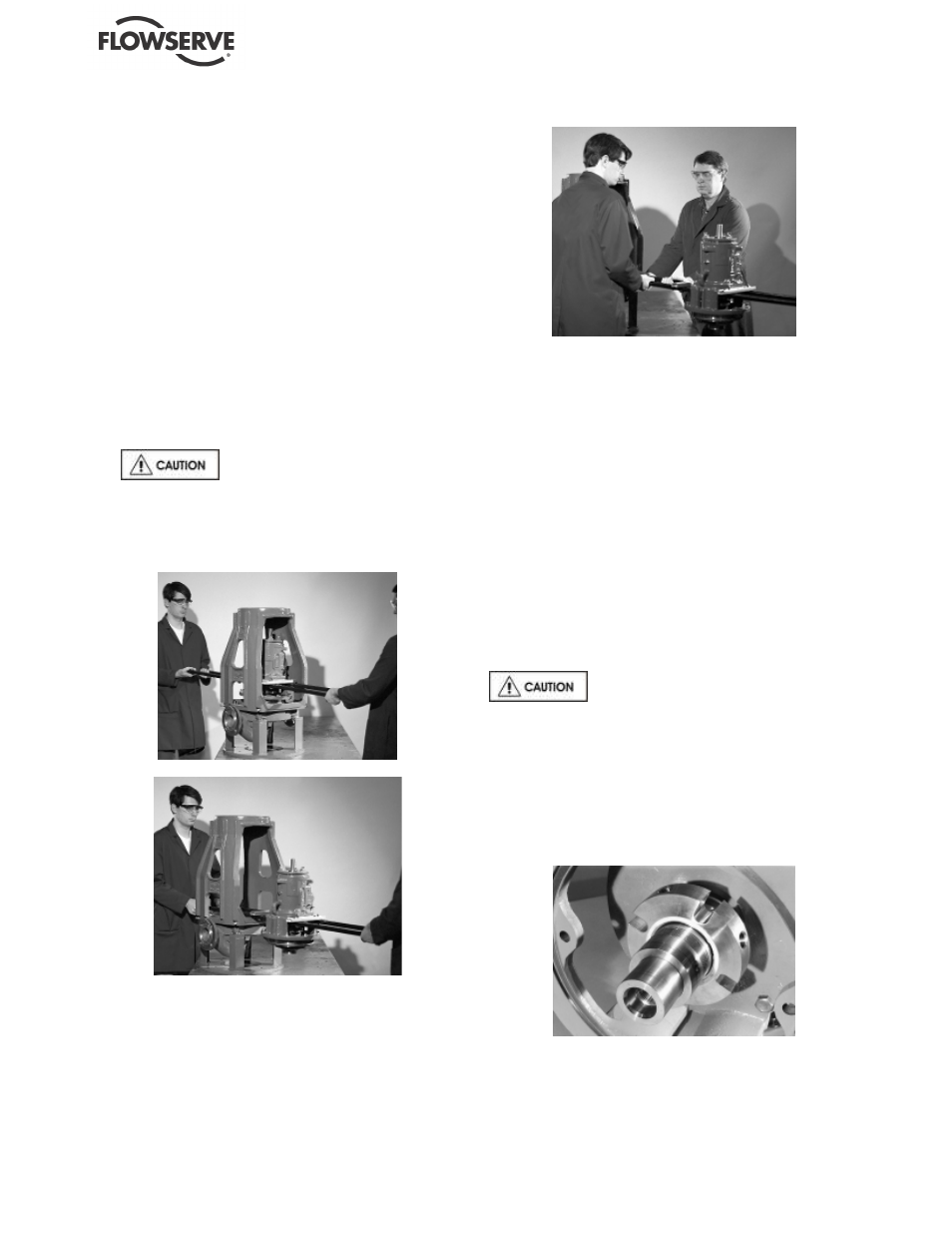
Move the power end, rear cover, and seal chamber
assembly away from the casing. On In-Line pumps
the simplest method of power end removal is to first
remove the motor and motor adapter with a crane.
However this is often not practical and the power
end must be removed by hand. This operation is
illustrated in figures 6-7, 6-8 and 6-9. Discard the
casing/cover gasket [4590.1].
The power end and rear cover
assembly is heavy. It is important to follow plant
safety guidelines when lifting it.
j)
Transport the assembly to the maintenance shop.
Figure 6.6
Figure 6.7
Figure 6.8
6.7.2
Pump disassembly
a) Remove the coupling hub from the pump shaft
[2100]. Close coupled pumps require the motor
adapter [3160] be removed.
b) Using the shaft key [6700], mount the impeller
wrench from the Flowserve Mark 3 tool kit (figure
6-1) to the end of the shaft. With the wrench
handle pointing to the left when viewed from the
impeller end, grasp the impeller [2200] firmly with
both hands (wear heavy gloves). By turning the
impeller in the clockwise direction move the
wrench handle to the 11 o’clock position and then
spin the impeller quickly in a counter-clockwise
direction so that the wrench makes a sudden
impact with a hard surface on the bench. After
several sharp raps, the impeller should be free.
Unscrew the impeller and remove from the shaft.
Discard the impeller gasket [4590.2].
Do not apply heat to the impeller. If
liquid is entrapped in the hub, an explosion could
occur.
c) If a cartridge type mechanical seal [4200] is used
(figure 6-10), the spacing clips or tabs should be
installed prior to loosening the set screws which
attaches the seal to the shaft or removing it from
the cover. This will ensure that the proper seal
compression is maintained.
Figure 6.9
d) Remove the seal or packing gland nuts [6580.2] if
so equipped.