3 impeller clearance, 4 direction of rotation, 5 guarding – Flowserve Mark 3 Sealed Metallic Durco User Manual
Page 39
MARK 3 USER INSTRUCTIONS ENGLISH 71569102 01-13
Page 39 of 72
flowserve.com
There are two inlet ports for In-Line pumps. In
addition to the connection described above a second
inlet is made at the 1/8in. NPT plugged port on the
bearing carrier [3240]. A vent fitting has been
supplied on the bearing carrier as well as a plugged
1/8 in. NPT bottom drain on the bearing housing for
Group 1 pumps and on the adapter [1340] for Group
2 pumps.
The pressure shall be 0.01-0.02 bar
(0.14-0.29 psi).
5.3 Impeller clearance
The impeller clearance was set at the factory based
on the application temperature at the time the pump
was purchased (see figure 5.12). For reverse-vane
and recessed impellers, the clearance is set to the
cover while the open impeller clearance is set to the
casing. If the process temperature changes the
impeller clearance must be reset, see section 6.6.
Figure 5.12: Impeller clearance settings
Temperature °C (°F)
Clearance mm (in.)
< 93 (200)
0.46 ± 0.08 (0.018 ± 0.003)
93 to 121 (200 to 250)
0.53 (0.021)
122 to 149 (251 to 300)
0.61 (0.024)
150 to 176 (301 to 350)
0.69 (0.027)
177 to 204 (351 to 400)
0.76 (0.030)
205 to 232 (401 to 450)
0.84 (0.033)
>232 (450)
0.91 (0.036)
Notes:
1. For 3x1.5-13 and 3x2-13 at 3500 rpm add 0.08 mm (0.003 in.).
2. Rotation of bearing carrier from center of one lug to center of
next results in axial shaft movement of 0.1 mm (0.004 in.).
3. Reverse vane impeller set to cover, open impeller to casing.
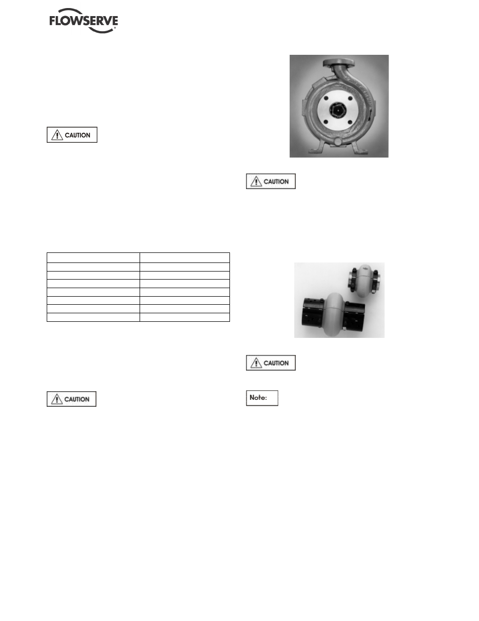
5.4 Direction of rotation
5.4.1
Rotation check
It is absolutely essential that the
rotation of the motor be checked before connecting
the shaft coupling. Incorrect rotation of the pump, for
even a short time, can dislodge and damage the
impeller, casing, shaft and shaft seal. All Mark 3
pumps turn clockwise as viewed from the motor end.
A direction arrow is cast on the front of the casing as
shown in figure 5.13. Make sure the motor rotates in
the same direction.
Figure 5.13
5.4.2
Coupling installation
The coupling (figure 5.14) should be
installed as advised by the coupling manufacturer.
Pumps are shipped without the spacer installed. If
the spacer has been installed to facilitate alignment,
then it must be removed prior to checking rotation.
Remove all protective material from the coupling and
shaft before installing the coupling.
Figure 5.14
5.5 Guarding
Power must never be applied to the
driver when the coupling guard is not installed.
In member countries of the EU and EFTA, it
is a legal requirement that fasteners for guards must
remain captive in the guard to comply with the
Machinery Directive 2006/42/EC. When releasing
such guards, the fasteners must be unscrewed in an
appropriate way to ensure that the fasteners remain
captive.
Flowserve coupling guards are safety devices intended
to protect workers from inherent dangers of the rotating
pump shaft, motor shaft and coupling. It is intended to
prevent entry of hands, fingers or other body parts into a
point of hazard by reaching through, over, under or
around the guard. No standard coupling guard provides
complete protection from a disintegrating coupling.
Flowserve cannot guarantee their guards will
completely contain an exploding coupling.