5 fastener torques – Flowserve Mark 3 Sealed Metallic Durco User Manual
Page 45
MARK 3 USER INSTRUCTIONS ENGLISH 71569102 01-13
Page 45 of 72
flowserve.com
6.5 Fastener torques
Figure 6-2: Recommended bolt torques for lubricated or PTFE coated fasteners
Item
Description
Group 1
Group 2
Group 3
[6570.12] Bearing retainer cap screws - standard bearings
n/a
n/a
5
/
16
in. – 16 Nm (12 lbf•ft)
[6570.12]
Bearing retainer cap
screws - duplex bearings
Standard Power End
3
/
16
in. – 6 Nm (4 lbf•ft)
3
/
16
in. – 6 Nm (4 lbf•ft)
5
/
16
in. –16 Nm (12 lbf•ft)
HD Power End
n/a
n/a
1
/
4
in. –11 Nm (8 lbf•ft)
[6570.5] Bearing housing/adapter cap screws and nuts
n/a
½ in. – 54 Nm (40 lbf•ft)
⅝
in. – 122 Nm (90 lbf•ft)
[6580.2]
Mechanical seal gland studs/nuts, with gasket
⅜
in. – 16 Nm (12 lbf•ft)
⅜
in. – 16 Nm (12 lbf•ft)
½ in. – 54 Nm (40 lbf•ft)
½ in. – 41 Nm (30 lbf•ft)
[6580.2]
Mechanical seal gland studs/nuts, with O-ring
⅜
in. – 27 Nm (20 lbf•ft)
⅜
in. – 27 Nm (20 lbf•ft)
½ in. – 54 Nm (40 lbf•ft)
½ in. – 54 Nm (40 lbf•ft)
[6580.1] Casing studs/nuts
½ in. – 41 Nm (30 lbf•ft)
½ in. – 41 Nm (30 lbf•ft)
⅝
in. – 81 Nm (60 lbf•ft)
¾ in. – 136 Nm (100 lbf•ft)
⅞
in. – 217 Nm (160 lbf•ft)
[6570.2] Cap screw cover/adapter (token bolts)
⅜
in. – 27 Nm (20 lbf•ft)
⅜
in. – 27 Nm (20 lbf•ft)
½ in. – 54 Nm (40 lbf•ft)
[6570.3] Bearing carrier set screws
⅜
in. – 16 Nm (12 lbf•ft)
½ in. – 41 Nm (30 lbf•ft)
½ in. – 41 Nm (30 lbf•ft)
[6570.4] Cap screw foot
Standard Power End
½ in. – 54 Nm (40 lbf•ft)
¾ in. – 217 Nm (160 lbf•ft)
1 in. – 300 Nm (228 lbf•ft)
HD Power End
n/a
n/a
½ in. – 54 Nm (40 lbf•ft)
[6570.13] Cap screws - repeller cover to cover
n/a
⅜
in. – 16 Nm (12 lbf•ft)
½ in. – 41 Nm (30 lbf•ft)
[6570.15] Cap screw – bearing housing
½ in. – 54 Nm (40 lbf•ft)
½ in. – 54 Nm (40 lbf•ft)
n/a
[3712]
Bearing Locknut –
Standard Power End –
27 +4/-0 Nm (20 +5/-0 lbf•ft) 54 +7 / -0 Nm (40 +5 / -0 lbf•ft)
95 +7 / -0 Nm (70 +5/-0 lbf•ft)
HD Power End
n/a
n/a
102 +7 / -0 Nm (75 +5/-0 lbf•ft)
Notes:
1. For non-lubricated/coated threads, add 25% to the values given above. 2. Gasket joint torque values are for unfilled PTFE gaskets. Other
gasket materials may require additional torque to seal. Exceeding metal joint torque values is not recommended
.
6.6 Setting impeller clearance and
impeller replacement
A new impeller gasket [4590.2] must be installed
whenever the impeller has been removed from the
shaft. Impeller clearance settings may be found in
section 5.3. Impeller balancing instruction may be
found in section 6.8.
Mark 3 Unitized Self-Priming pumps
required that the outside diameter of the impeller be
3mm (0.125 in.) from the casing cutwater. If this
close clearance is not maintained the pump may not
prime.
Do not adjust the impeller clearance with the seal set.
Doing so may result in seal leakage and/or damage.
The impeller could have sharp edges,
which could cause an injury. It is very important to
wear heavy gloves.
It is recommended that two people
install a Group 3 impeller. The weight of a Group 3
impeller greatly increases the chance of thread
damage and subsequent lock-up concerns.
Do not attempt to tighten the impeller
on the shaft by hitting the impeller with a hammer or
any other object or by inserting a pry bar between the
impeller vanes. Serious damage to the impeller may
result from such actions.
Care should be taken in the handling
of high chrome iron impellers
Install the impeller [2200] by screwing it onto the
shaft (use heavy gloves) until it firmly seats against
the shaft shoulder.
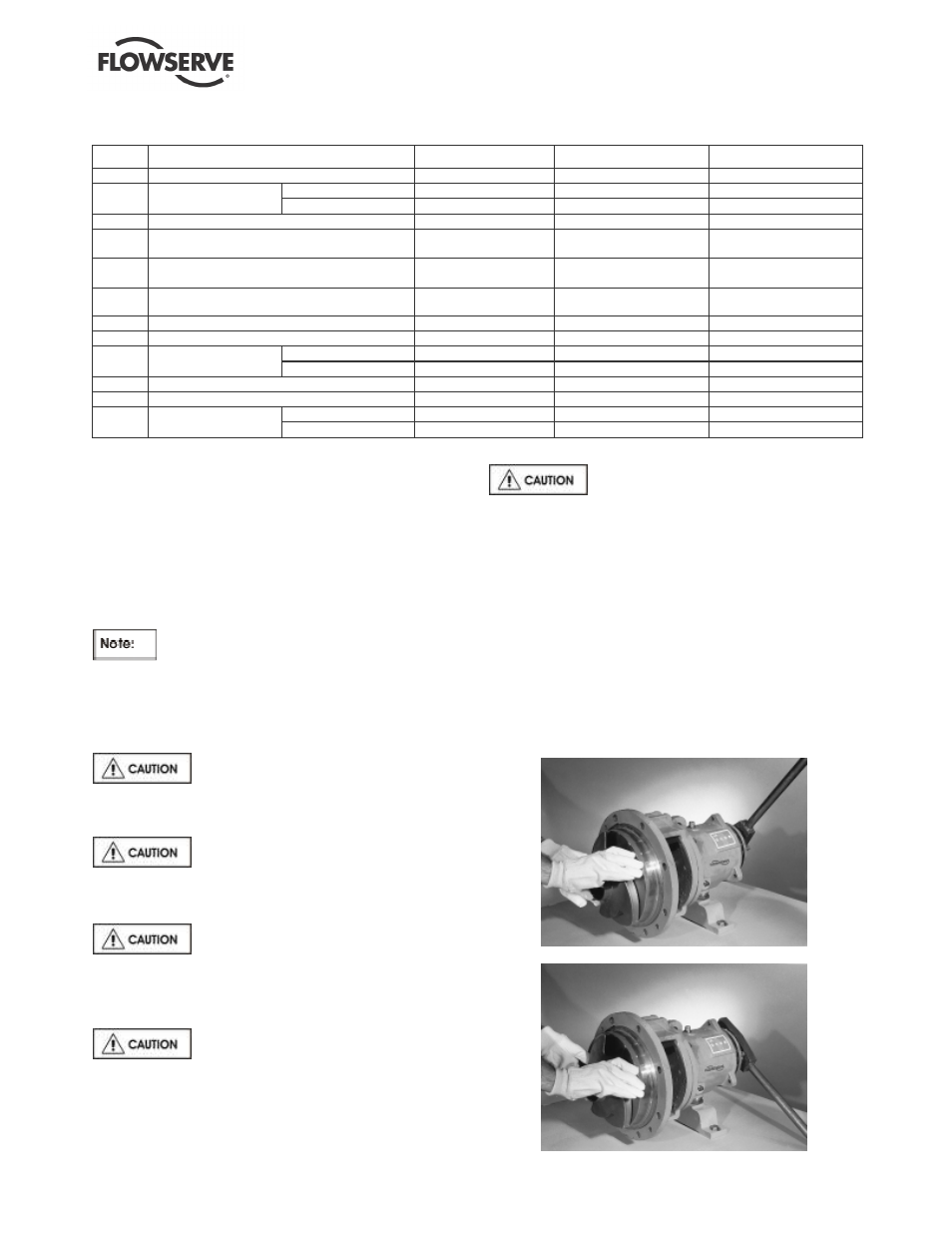
Tighten the impeller with the impeller wrench from the
Flowserve Mark 3 tool kit. To do this, grasp the
impeller in both hands and, with the impeller wrench
handle to the left (viewed from the impeller end of the
shaft - figure 6-3) spin the impeller forcefully in a
clockwise direction to impact the impeller wrench
handle on the work surface to the right (figure 6-4).
Figure 6.2
Figure 6.3