Flowserve Mark 3 Sealed Metallic Durco User Manual
Page 49
MARK 3 USER INSTRUCTIONS ENGLISH 71569102 01-13
Page 49 of 72
flowserve.com
e) Remove the cover.
All pumps except Sealmatic
Remove the two cap screws [6570.2] which
attach the rear cover [1220] to the adapter.
Carefully remove this part.
Sealmatic pump only
Remove the cap screws that hold the rear cover
[1220] to the repeller cover [1220.1]. For Group
3 pumps remove the capscrews [6570.2] that
hold the rear cover [1220] to the adapter [1340].
Remove the cover. The repeller is now exposed
[2200.1] and should be free to slip from the shaft.
In the event it is stuck, the repeller can be pried
off by the use of 2 screwdrivers wedged between
the repeller [2200.1] and the repeller cover
[1220.1].
f) If a component type inside mechanical seal
[4200] is used, loosen the set screws on the
rotating unit and remove it from the shaft (see
figure 6-11). Then pull the gland [4120] and
stationary seat off the shaft. Remove the
stationary seat from the gland. Discard all
O-rings and gaskets.
Figure 6.10
g) If a component type outside mechanical seal is
used, remove the gland and the stationary seat.
Remove the stationary seat from the gland.
Loosen the set screws in the rotating unit and
remove it from the shaft. Discard all O-rings and
gaskets.
h) If packing [4130] is used, remove it and the seal
cage [lantern ring, 4134]. Remove the gland
[4120].
i)
If the pump has a hook type sleeve [2400] it can
now be removed. Unit now appears as shown in
figure 6-12.
Figure 6.11
j)
If the power end is oil lubricated, remove the
drain plug [6569.1] and drain the oil from the
bearing housing [3200].
k) If the pump has lip seals, a deflector [2540] will
be present. Remove it.
l)
Loosen the three set screws [6570.3] on the
bearing carrier [3240]. The bearing carrier must be
completely unscrewed from the bearing housing.
Do not pry against the shaft.)
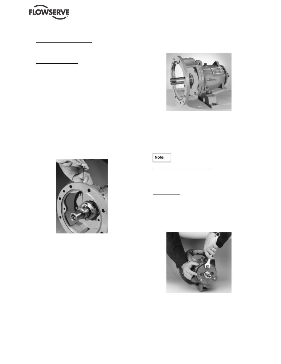
Mark 3A and ANSI 3A design
The face of the bearing carrier has three square
lugs that protrude from the surface. The bearing
carrier is turned by using an open end wrench on
one of the square lugs as shown in figure 6-13.
Mark 3 design
On Group 1 and 2 pumps the bearing carrier is
turned by using a strap wrench, with the strap
located around the outside diameter of the carrier
face. On Group 3 pumps, the bearing carrier is
turned by using a spanner wrench to engage the
cogs on the outside diameter of the bearing carrier.
Figure 6.12