Flowserve Mark 3 Sealed Metallic Durco User Manual
Page 46
MARK 3 USER INSTRUCTIONS ENGLISH 71569102 01-13
Page 46 of 72
flowserve.com
6.6.1
Installation and clearance setting for
reverse vane impellers on Mark 3
Standard, Unitized self-priming, In-Line
and open vane impeller on the Recessed
impeller pump
Flowserve reverse vane impellers and Recessed
open impellers are set off the cover. This allows the
impeller to be set without the casing.
Set the impeller clearance by loosening the set
screws [6570.3] and rotating the bearing carrier
[3240] to obtain the proper clearance. Turn the
bearing carrier counter-clockwise until the impeller
comes into light rubbing contact with the rear cover.
Rotating the shaft at the same time will accurately
determine this zero setting. Now, rotate the bearing
carrier clockwise to get the proper clearance. Refer
to figure 5.12 for the proper impeller clearance based
on the operating temperature for the application.
Rotating the bearing carrier the width of one of the
indicator patterns cast into the bearing carrier moves
the impeller axially 0.1 mm (0.004 in.). (See figure 6-5.)
Figure 6.4
Determine how far to rotate the bearing carrier by
dividing the desired impeller clearance by 0.1 mm
(0.004 in.) (one indicator pattern). Tightening the set
screws [6570.3] will cause the impeller to move 0.05
mm (0.002 in.) closer to the rear cover because of the
internal looseness in the bearing carrier threads. This
must be considered when setting the impeller
clearance. Rotate the bearing carrier clockwise the
required amount to get the desired clearance to the
cover.
Lastly, uniformly tighten the set screws
[6570.3] in incremental steps up to the final torque
value to lock the bearing carrier in place.
Figure 6.5
Example: If a pump was to be placed in a service with
an operating temperature of 100 °C (212 °F) the
impeller setting would be 0.53 mm (0.021 in.) off the
rear cover plate. Since it is necessary to add 0.05 mm
(0.002 in.) for the movement caused by tightening the
set screws an adjustment of 0.58 mm (0.023 in.) is
needed. First turn the bearing carrier counter-clockwise
until the impeller comes into light rubbing contact with
the rear cover. To determine the number of indicator
patterns that you will need to rotate the carrier, divide
0.10 into the desired setting;
0.58 / 0.10 = 5.8 (0.023 / 0.004 = 5.8). Rotate the
bearing carrier clockwise 6 indicator patterns which
will give a clearance of 0.60 mm (0.024 in.).
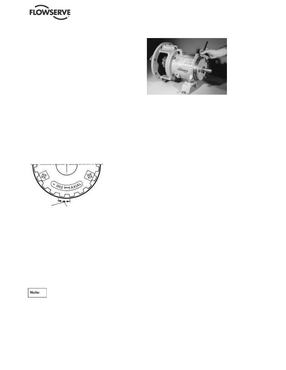
Flowserve suggests that a felt tip pen be used to
mark an initial reference point on the bearing housing
and the bearing carrier as shown in figure 6-6.
Then make a second mark on the bearing carrier 6
indicator patterns counter-clockwise from the initial
reference point. Rotate the bearing carrier clockwise
until the second mark on the bearing carrier lines up
with the initial reference point mark on the bearing
housing. Lastly, uniformly tighten the set screws
[6570.3] in incremental steps up to the final torque
value to lock the bearing carrier in place.
6.6.2
Installation and clearance setting for front
vane open style impeller on Mark 3
Standard, Unitized self-priming, Lo-Flo,
and Inline pumps
Like all front vane open style impellers, the Flowserve
open impeller clearance must be set off the casing.
The casing must be installed to accurately set the
impeller clearance. (Realizing that this can be very
difficult, Flowserve strongly promotes the use of
reverse vane impellers, which do not require the
presence of the casing to be properly set.)
Attach the power end/rear cover plate assembly to the
casing. Now set the impeller clearance by loosening
the set screws [6570.3] and rotating the bearing carrier
[3240] to obtain the proper clearance. Turn the bearing
carrier clockwise until the impeller comes into light
Rotation Equivalent To
0.1 mm (0.004 in) Axial
Movement
Indicator
Pattern