Flowserve FRBH User Manual
Page 12
FRBH, FRBHX AND FRBHS USER INSTRUCTIONS ENGLISH 71569178 10-04
Page 12 of 54
®
2.5 Recycling and end of product life
At the end of the service life of the product or its parts,
the relevant materials and parts should be recycled or
disposed of using an environmentally acceptable
method and in accordance with local regulations. If the
product contains substances that are harmful to the
environment, these should be removed and disposed of
in accordance with current local regulations. This also
includes the liquids and/or gases that may be used in
the "seal system" or other utilities.
Make sure that hazardous substances are
disposed of safely and that the correct personal
protective equipment is used. The safety specifications
must be in accordance with the current local
regulations at all times.
3 PUMP DESCRIPTION
3.1 Configurations
Flowserve "FRBH" pumps are single stage, end
suction centrifugal pumps specifically designed for the
pulp and paper industry and consequently are ideally
suited to many process fluids. A volute type casing
with integrally cast feet and top centerline discharge
nozzle is standard. The semi-open impeller with rear
pump-out vanes is capable of passing pulpy material
and solids of a limited size. Sealing is provided at the
impeller to shaft fit to prevent corrosion and thereby
facilitate impeller removal. The rigid three point thrust
bearing housing support permits precision bearing
alignment. The back pull-out feature, typical of all
FRBH pumps, permits quick removal of the entire
rotor/frame assembly without disturbing the casing or
driver.
The pump is sealed using non-asbestos packing in the
stuffing box. An optional hydrodynamic seal,
commonly referred to as an expeller is available and
various mechanical seal designs as specifi ed by the
customer may be installed at the factory or retrofitted in
the field.
All pumps are carefully inspected and prepared for
shipment. All exterior machined surfaces are coated
with a rust preventative compound and openings are
provided with covers or plugs. Shaft packing, when
required, is shipped with the pump and should not be
installed until the pump is ready to run. Mechanical
seals, when provided, are factory installed and adjusted
prior to shipment. The axial impeller running clearance
is preset at the factory but should be checked prior to
final alignment in case of tampering.
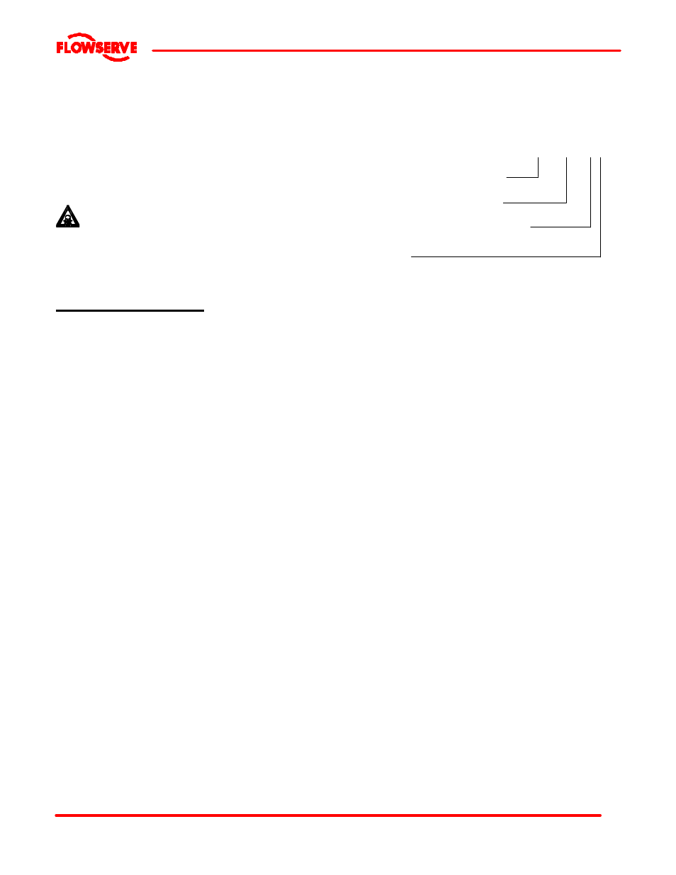
3.2 Name nomenclature
The pump size will be engraved on the nameplate. The
following example explains how the pump name
identifies the construction features and options.
8FRBH-182
Nominal discharge branch size.
Configuration – see below.
Nominal maximum impeller diameter.
Frame size
S
is added for a recessed impeller
X
is added for an expeller
3.3 Design of major parts
3.3.1 Pump casing
The pump casing is a volute type casing with integrally
cast feet and top centerline discharge nozzle. It is a
one piece pressure retaining casting with gasket
connections to the stuffing box head and the suction
and discharge flanges.
3.3.2 Impeller
The impeller is semi-open design, keyed to the shaft
and secured with a contoured impeller nut. The vanes
of the impeller are Francis type however, the “S”
configuration utilizes straight radial vanes to reduce
blockage. The impeller of the FRBHS pump is recessed
away from volute to reduce shear.
3.3.3 Shaft
The large diameter stiff shaft, mounted on bearings,
has a keyed drive end.
3.3.4 Pump bearings and lubrication
Ball bearings are fitted as standard and may be either
oil or grease lubricated.
Oil lubrication is only available where the pump shaft is
horizontal.
3.3.5 Bearing housing
For oil lubricated bearings, a bulls eye level gauge is
supplied. Constant level oilers can also be fitted. Two
grease nipples enable grease lubricated bearings to be
replenished between major service intervals.