Flowserve FRBH User Manual
Page 37
FRBH, FRBHX AND FRBHS USER INSTRUCTIONS ENGLISH 71569178 10-04
Page 37 of 54
®
push the inner race only. Note that the bearing must
remain square to the shaft during assembly and that
the inner race must seat on the shaft shoulder.
Protect the bearing by wrapping with a clean, lint free
cloth.
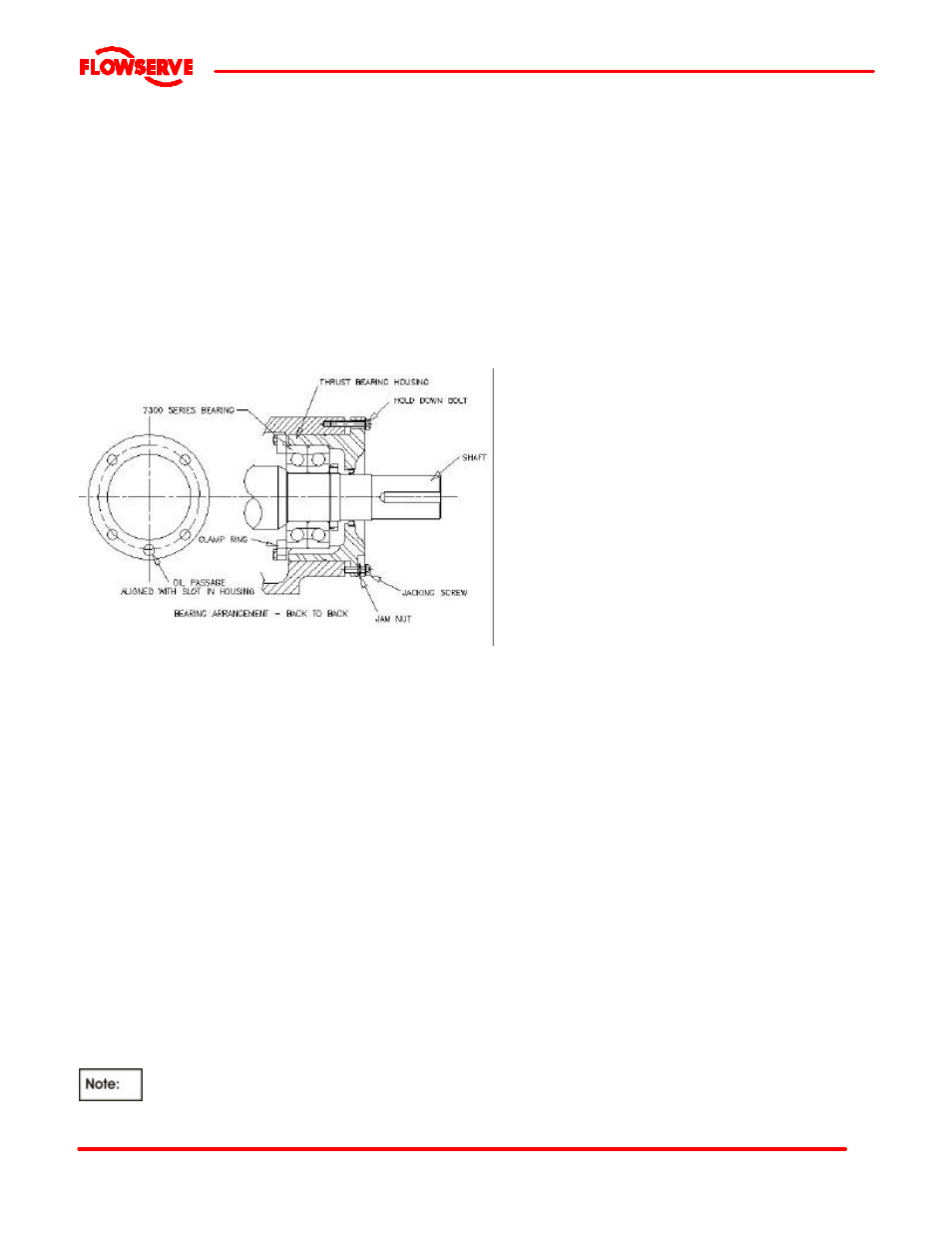
6.10.3 Thrust bearing
a) Pack thrust bearing with grease if the bearings are
being grease lubricated.
b) Place the thrust bearing clamp ring [37] loosely over
the shaft on the largest diameter.
c) Install the angular contact bearings [18] on the shaft
[6] using the same procedure as described in step
6.10.2 . The bearings are mounted back to back as
shown.
d) Slide the bearing lockwashers [22A] on the shaft and
fit the bearing locknut [22]. Tighten the locknut
snugly and allow to cool. Check the tightness and
bend one tab on the lockwasher into a slot in the
locknut. Protect the bearings from contamination.
e) Carefully install the lip seal [49] in the thrust bearing
housing [33] by pressing it squarely into the bore.
The primary sealing lip [spring loaded] on seal
should be installed facing the bearing. A small
amount of sealant may be applied on the O.D. of the
seal prior to its' installation.
f) Install the square head plug or grease fitting on the
tapped hole in the thrust bearing housing flange.
Lubricate the o-ring [89B] with the bearing lubricant
and assemble it into the groove of the outer
circumference of the thrust bearing housing [33].
g) Lubricate the inside bore of the thrust bearing
housing [33] and assemble it over the thrust
bearings. Care must be taken to prevent damage of
the seal on the shaft.
h) Using capscrews and lockwashers, attach the thrust
bearing clamp ring [37] to the thrust bearing housing
[33]. Lock the threads using Loctite 242 or
equivalent.
The thrust bearing clamp ring [37] is provided
with one extra hole midway between two adjacent bolt
holes to permit free oil flow. On oil lubricated units, this
hole must align with the cast oil return at the bottom of
the thrust bearing housing bore. For grease lubricated
units, this hole should be oriented away from the cast oil
return slot at the bottom the thrust bearing housing bore.
Tighten the capscrews evenly ensuring that the clamp
ring is not distorted and gap to the bearing housing is
even all around. Tighten in accordance with Table 6.6.
6.10.4 Frame assembly
6.10.4.1 Frame 1, 2 & 3
a) Place the bearing frame in a vertical position with the
large flange resting on wooden support blocks
sufficiently high to allow the shaft from contacting the
floor when it is installed.
b) Lift the shaft assembly into a vertical position and
lower it into the bearing frame [19]. Note the square
head plug (or grease fitting in the thrust bearing
housing [33] must align with the vent lug [213] in the
frame [19].
6.10.4.2 Frame 4 for 18FRBH274 & 20FRBH304
only
a) Assemble the adapter [71] to the bearing frame [19].
6.10.4.3 Frame 4 only
a) Place the shaft assembly in a vertical position with
the thrust bearing housing [33] resting on the flange
face and supported by blocks or clamps. Access to
one through hole in the thrust bearing housing is
required to attach one bolt.
b) Lift the bearing frame assembly [19] vertically and lower
over the shaft assembly. Manually guide the line
bearing outer race into the bearing frame bore. Ensure
that the thrust bearing housing [33] and frame [19] are
oriented as in Step 6.10.4.1 b). This will ensure that the
oil return slot in the thrust bearing housing [33] is
properly located.
6.10.4.4 All frames
a) Install at least one thrust bearing housing to bearing
frame hold down capscrews complete with
lockwasher to prevent the assembly from coming
apart when lifting.
b) Place the bearing frame assembly into a horizontal
position.
c) Install the remaining capscrews and lockwashers.
Assemble the jam nuts on the jacking screws and
assemble these into the thrust bearing housing [33].
d) Carefully install the lip seal [47] in the line bearing
cover [35] by pressing it squarely into the bore. The
primary sealing lip [spring loaded] on seal should be
installed facing the bearing. A small amount of
sealant may be applied on the O.D. of the seal prior
to its' installation.
e) Lubricate the o-ring [89A] and assemble into the
groove of the line bearing cover.