Flowserve FRBH User Manual
Page 34
FRBH, FRBHX AND FRBHS USER INSTRUCTIONS ENGLISH 71569178 10-04
Page 34 of 54
®
6.3 Spare parts
6.3.1 Ordering of spares
Flowserve keep records of all pumps that have been
supplied. When ordering spares the following
information should be quoted:
1) Pump serial number
2) Pump size
3) Part name – taken from section 8
4) Part number – taken from section 8
5) Number of parts required
The pump size and serial number are shown on the
pump nameplate.
To ensure continued satisfactory operation,
replacement parts to the original design specification
should be obtained from Flowserve.
Any change to the original design specification
(modification or use of a non-standard part) will
invalidate the pump’s safety certification.
6.3.2 Storage of spares
Spares should be stored in a clean dry area away
from vibration. Inspection and re-treatment of metallic
surfaces (if necessary) with preservative is
recommended at 6 monthly intervals.
6.4 Recommended spares and consumable items
For start up purposes:
1 - complete set of gland packing
2 - shaft sleeves
1 - set of gaskets and seals
(optional: 2 - mechanical seals)
For 2 years operation:
1 - set of bearings (line and thrust)
2 - sets of gland packing
2 - shaft sleeves
2 - sets of gaskets and seals
2 - lantern rings
2 - casing wear rings
(optional: 2 - mechanical seals
2 - impeller wear rings)
For 4 years operation:
1 - set of bearings (line and thrust)
2 - sets of gland packing
2 - shaft sleeves
2 - sets of gaskets and seals
2 - lantern rings
2 - casing wear rings
1 - impeller
(optional: 2 - mechanical seals
1 - wearplate)
6.5 Tools required
A typical range of tools that will be required to
maintain these pumps is listed below.
Readily available in standard tool kits, and dependent
on pump size:
•
Open ended spanners (wrenches) to suit up to
M 48 screws/nuts
•
Socket spanners (wrenches), up to M 48 screws
•
Allen keys, up to 10 mm (A/F)
•
Range of screwdrivers
•
Soft mallet
More specialized equipment:
•
Bearing pullers
•
Bearing induction heater
•
Dial test indicator
•
C-spanner (wrench) - for removing shaft nut.
(If difficulties in sourcing are encountered, consult
Flowserve.)
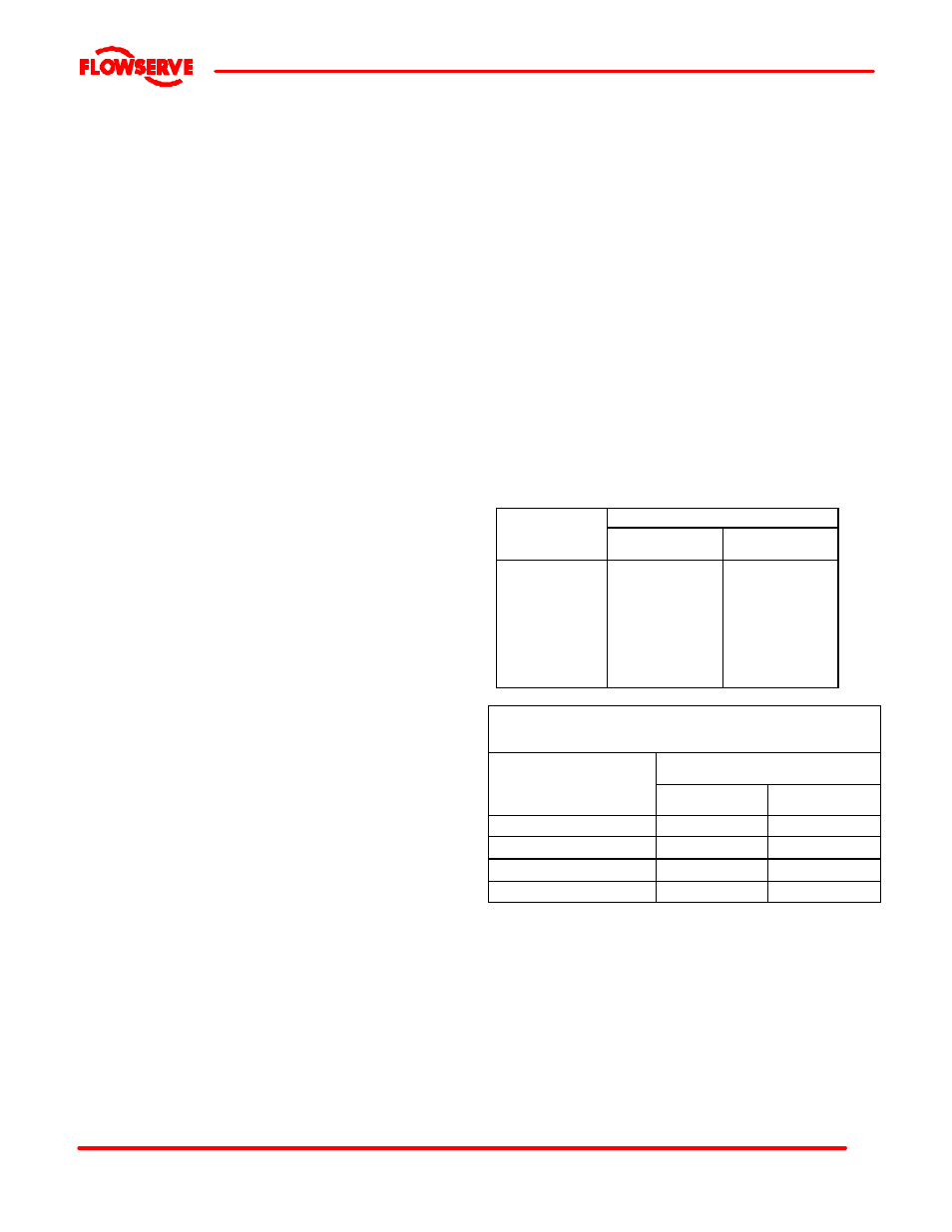
6.6 Fastener torques
Torque Nm (lb
Ÿft)
Bolt size
Pump feet
fasteners
All other
fasteners
M 16 (? in.)
M 20 (¾ in.)
M 24 (? in.)
M 27 (1 in.)
M 30 (1? in.)
M 36 (1? in.)
M 42 (1? in.)
M 48 (1? in.)
170 (125)
340 (250)
590 (435)
770 (570)
1 100 (810)
1 840 (1 350)
2 000 (1 475)
2 240 (1 650)
84 (62)
165 (120)
285 (210)
375 (275)
540 (400)
900 (660)
1 410 (1 040)
2 060 (1 500)
TIGHTENING TORQUE FOR STAINLESS STEEL STUDS
WITH LUBRICATED THREADS
THREAD SIZE
TIGHTENING TORQUE
Nm.
Ft. lbs.
M10x1.5 (3/8–16UNC)
13
10
M12x1.75 (1/2–13UNC)
27
20
M16X2 (5/8-11UNC)
60
45
M20x2.5 (¾-10UNC)
100
75
6.7 Renewal clearances
As wear takes place between the impeller and casing
ring the overall efficiency of the pump set will
decrease. To maintain optimum efficiency it is
recommended that rings are replaced and the impeller
renovated when the radial clearance detailed in
section 3.4.2 has doubled to 0.6 to 0.8 mm (0.024 to
0.032 in.), depending on pump size.