Flowserve FRBH User Manual
Page 13
FRBH, FRBHX AND FRBHS USER INSTRUCTIONS ENGLISH 71569178 10-04
Page 13 of 54
®
3.3.6 Stuffing box housing
The stuffing box housing has a spigot (rabbet) fit
between the pump casing and bearing housing for
optimum concentricity. The design enables a number
of sealing options to be fitted.
3.3.7 Shaft seal
The mechanical seal(s), attached to the pump shaft,
seals the pumped liquid from the environment. Gland
packing may be fitted as an option. The “FRBHX”
model is fitted with an optional dynamic or expeller seal
for certain applications.
3.3.8 Driver
The driver is normally an electric motor. Different drive
configurations may be fitted such as internal
combustion engines, turbines, hydraulic motors etc
driving via couplings, belts, gearboxes, drive shafts etc.
3.3.9 Accessories
Accessories may be fitted when specified by the
customer.
3.4 Performance and operating limits
This product has been selected to meet the specifications
of your purchase order see section 1.5. The following data
is included as additional information to help with your
installation. It is typical, and factors such as temperature,
materials, and seal type may influence this data. If
required, a definitive statement for your particular
application can be obtained from Flowserve.
3.4.1 Operating limits
Pumped liquid temperature limits
up to+177 ºC (350 ºF)
Maximum ambient temperature
up to +50 ºC (122 ºF)
Maximum soft solids in suspension
up to 7 % by volume
Maximum pump speed
Refer to the nameplate
3.4.2 Speed torque curves
To bring a centrifugal pump up to rated speed, the
driver must be capable of providing more torque at
each speed than required by the pump. The margin
between the available and required torque affects the
time it takes the unit to reach full speed. If the torque
required by the pump exceeds the torque capability of
the drive at any run-up speed, the unit will not
accelerate to full speed. Normally, this is not a problem
with standard induction or synchronous motors
provided the proper voltage is supplied at the motor.
For pumps started at shut valve conditions, 100 percent
full speed torque can be calculated by using the
formula:
Torque (Nm) = 9545 Shutoff Power (kW)
r/min
Torque (lbfx ft) = 5250 Shutoff Power (hp)
r/min
Torque required by the pump at any other speed during
start-up can be determined from the curve above. Note
that the driver manufacturer usually bases 100 percent
torque on the design power of the driver and
consequently the speed-torque curves should be
plotted in torque units (e.g. Nm) instead of percentage
torque to avoid confusion.
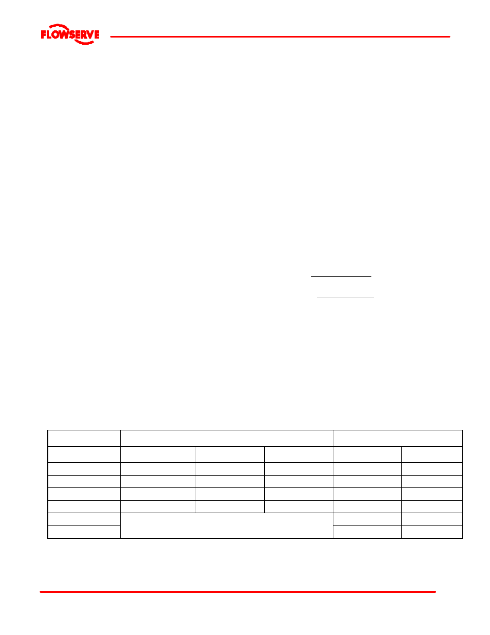
3.4.3 MAXIMUM WORKING PRESSURES -bar (psi).
CONSTRUCTION
CAST IRON AND C.I.S.S. FITTED
STAINLESS STEEL
316,317L, WORTHITE, ETC.
TEMPERATURE
O
C (
O
F)
UP TO 12”
DISCHARGE
14 TO 16”
DISCHARGE
18 TO 20”
DISCHARGE
UP TO 16”
DISCHARGE
18 TO 20”
DISCHARGE
-30 to 38 (-20 to100)
10.3 (150)
10.3 (150)
6.2 (90)
13.8 (200)
8.3 (120)
65 (150)
10.3 (150)
9.7 (140)
6.2 (90)
13.8 (200)
8.3 (120)
95 (200)
10.3 (150)
9.3 (135)
6.2 (90)
13.4 (195)
8.3 (120)
120 (250)
10.3 (150)
9.0 (130)
6.2 (90)
12.6 (185)
8.3 (120)
150 (300)
12.1 (175)
8.3 (120)
175 (350)
Consult factory for applications in this range. Cast
iron not recommended due to thermal shock risks.
11.0 (160)
7.6 (110)