Flowserve FRBH User Manual
Page 39
FRBH, FRBHX AND FRBHS USER INSTRUCTIONS ENGLISH 71569178 10-04
Page 39 of 54
®
6.10.7 Wearplate
a) Install the studs [209A] in the wearplate [181] using
Loctite grade A or equivalent. Place the sealing
washer [197] over the studs [209A] and install the
wearplate into the casing [1]. Secure wearplate
[181] in place using hex nuts and washers using
Loctite 242 or equivalent. Tighten in accordance
with Table tables in section 6.6.
Excessive or uneven tightening torque may distort wearplate
affecting impeller running clearances or result in broken
studs.
b) Stand the casing on it's feet.
c) Smear a small amount of grease or anti-seize
compound over one face of the gasket [73] and
place it on the stuffing box head [11] with coated
face against flange.
Some sizes, as identified in Section I use an o-
ring in place of a gasket.
6.10.8 FRBHS only
a) Take spacer [71] and install gasket [73] with a small
amount of grease on the face that will mate inside
the casing [1].
b) Smear anti-seize compound on the casing [1] and
adapter [71] rabbit fit (spigot) diameters to ease
assembly and future disassembly.
c) Install the adapter/gasket [71/73] into the casing [1].
This piece is loose so caution must be
exercised when moving around the casing.
6.10.9 All pumps except FRBHS
a) Smear anti-seize compound on the casing [1] and
stuffing box head [11] rabbit fit (spigot) diameters to
ease assembly and future disassembly.
6.10.10 Rotor unit
a) With a sling around the bearing frame placed so as
to balance the weight, lift the frame/impeller
assembly keeping the shaft horizontal.
b) Install the frame/impeller assembly into the casing [1]
by guiding the stuffing box head and bearing frame
spigots squarely into the casing recess. Ensure that
the gasket [73] stays in position. If the fit becomes
snug, use 4 equally spaced bolts to draw the
assembly into the casing.
c) Install the casing frame bolts with washers and
tighten in accordance with Table 6.6.
d) Using the thrust bearing housing adjustment feature
[Figure 8], move the impeller forward away from the
stuffing box head [11].
e) Attach the bearing frame support [191] to the bearing
frame [19] using the capscrews and washers. Ensure
that thread engagement is atleast 1 diameter. Use
Loctite 242 thread sealant.
lockwashers should not be used to
ensure proper thread engagement with standard
bolting.
f) Set the impeller front clearance in accordance with
instruction earlier in this section of the manual.
6.10.11 Shaft seal
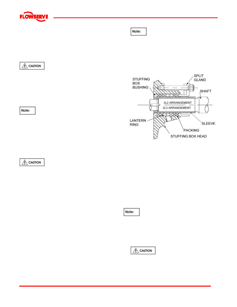
6.10.11.1 Packing
Standard Packed Box Arrangement
a) Insert one packing ring at a time into the stuffing box.
Push the packing as far as possible into the packing
bore.
b) Install additional rings as required, staggering the
joints.
c) Once the first two or three rings of packing have
been inserted, the two piece lantern ring [29] must
be installed. Push the lantern ring and previously
installed packing. The ports in the lantern ring do not
need to be aligned with the inlet/outlet ports.
d) Ensure that the shaft can be turned by hand.
e) Install the remaining rings of packing, alternating the
joints.
It may not be possible to insert the last ring in
the box and still insert the gland. In this case, omit
the last ring of packing and install the gland. The last
ring of packing should be installed after the pump
has been in service and sufficient space is available.
f) Install the gland halves [17], tighten the gland nuts
[215] only finger tight.
New packing has to be run-in and it
is good practice to start the pump with the stuffing
box gland quite loose. Packing that is too tight in the
box will cause undue friction, creating heat which will
glaze the packing and possible score the shaft
sleeves. To be effective, the packing must remain