Flowserve FRBH User Manual
Page 25
FRBH, FRBHX AND FRBHS USER INSTRUCTIONS ENGLISH 71569178 10-04
Page 25 of 54
®
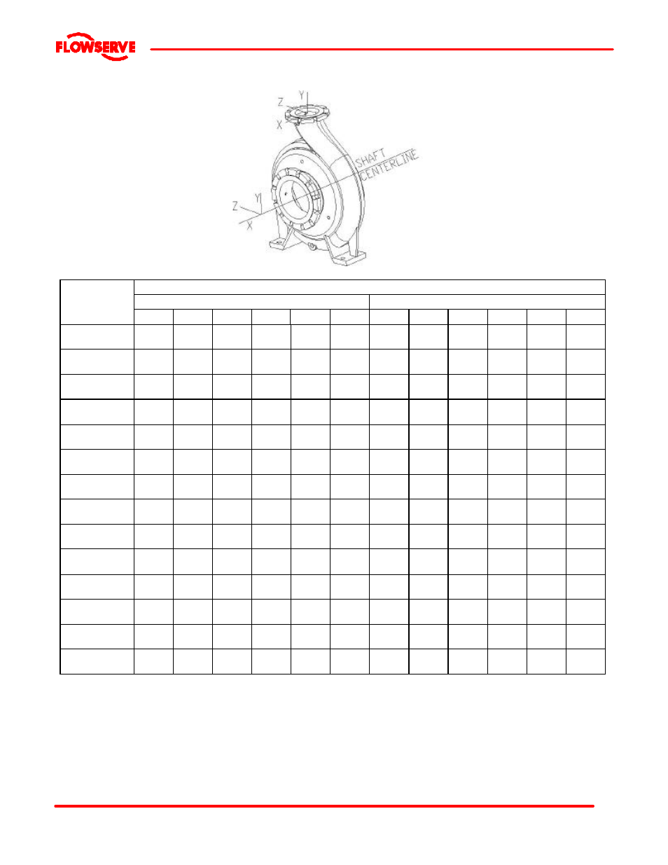
4.7.2
Maximum forces and moments allowed on FRBH pump flanges
Maximum forces (F) in N (lbf) and moments (M) in Nm (lbf•ft)
Suction
Discharge
Flange Size
DN
(in.)
Mx
My
Mz
Fx
Fy
Fz
Mx
My
Mz
Fx
Fy
Fz
50
(2)
460
(340)
230
(170)
350
(260)
890
(200)
710
(160)
5808
(130)
460
(340)
230
(170)
350
(260)
710
(160)
580
(130)
890
(200)
65
(2-1/2)
710
(520)
350
(260)
540
(400)
1110
(250)
890
(200)
760
(170)
710
(520)
350
(260)
540
(400)
890
(200)
760
(170)
1110
(250)
80
(3)
950
(700)
470
(350)
720
(530)
1330
(300)
1070
(240)
890
(200)
950
(700)
470
(350)
720
(530)
1070
(240)
890
(200)
1330
(300)
100
(4)
1330
(980)
680
(500)
1000
(740)
1780
(400)
1420
(320)
1160
(260)
1330
(980)
680
(500)
1000
(740)
1420
(320)
1160
(260)
1780
(400)
125
(5)
1830
(1340)
940
(690)
1450
(1070)
2450
(550)
1960
(440)
1600
(360)
1830
(1340)
940
(690)
1450
(1070)
1960
(440)
1600
(360)
2450
(550)
150
(6)
2300
(1700)
1180
(870)
1760
(1300)
3110
(700)
2490
(560)
2050
(460)
2300
(1700)
1180
(870)
1780
(1300)
2490
(560)
2050
(460)
3110
(700)
200
(8)
3530
(2600)
1760
(1300)
2580
(1900)
4890
(1100)
3780
(850)
3110
(700)
3530
(2600)
1760
(1300)
2580
(1900)
3780
(850)
3110
(700)
4890
(1100)
250
(10)
5020
(3700)
2440
(1800)
3800
(2800)
6670
(1500)
5340
(1200)
4450
(1000)
5020
(3700)
2440
(1800)
3800
(2800)
5340
(1200)
4450
(1000)
6670
(1500)
300
(12)
6100
(4500)
2980
(2200)
4610
(3400)
8000
(1800)
6670
(1500)
5340
(1200)
6100
(4500)
2980
(2200)
4610
(3400)
6670
(1500)
5340
(1200)
8000
(1800)
350
(14)
6370
(4700)
3120
(2300)
4750
(3500)
8900
(2000)
7120
(1600)
5780
(1300)
6370
(4700)
3120
(2300)
4750
(3500)
7120
(1600)
5780
(1300)
8900
(2000)
400
(16)
7320
(5400)
3660
(2700)
5420
(4000)
10230
(2300)
8450
(1900)
6670
(1500)
7320
(5400)
3660
(2700)
5420
(4000)
8450
(1900)
6670
(1500)
10230
(2300)
450
(18)
8200
(6050)
4200
(3100)
6100
(4500)
11570
(2600)
9650
(2170)
7560
(1700)
8200
(6050)
4200
(3100)
6100
(4500)
9610
(2160)
7560
(1700)
11570
(2600)
500
(20)
9080
(6700)
4750
(3500)
6780
(5000)
12900
(2900)
10720
(2410)
8450
(1900)
9080
(6700)
4750
(3500)
6780
(5000)
10760
(2420)
8450
(1900)
12900
(2900)
550
(24)
10850
(8000)
5830
(4300)
8130
(6000)
15480
(3480)
13120
(2950)
10230
(2300)
10850
(8000)
5830
(4300)
8130
(6000)
13080
(2940)
10230
(2300)
15660
(3520)
Notes:
1) F = External force (tension or compression) M = External
moment, clockwise or counter-clockwise
2) Forces and moments may be applied simultaneously in any
direction
3) Values apply to all materials
4) Higher loads may be applicable, if direction and magnitude of
individual loads are known, but these need written approval from
Flowserve
5) Pumps must be on rigid foundations and baseplates must be
fully grouted
6) Pump/baseplate should not used as pipe anchor. Expansion
joints must be properly tied
7) The pump mounting bolt torques specified must be used to
prevent relative movement between the pump casing and
baseplate. (See section 6.6, Fastener torques.) The bolt material
must have a minimum yield strength of 600 N/mm
2
(87 000 lb/in.
2
)