2 setting procedure (refer to figure 3.2) – Flowserve UEX Limitorque User Manual
Page 11
11
Limitorque UEX FCD LMENIM1205-03-AQ – 05/15
flowserve.com
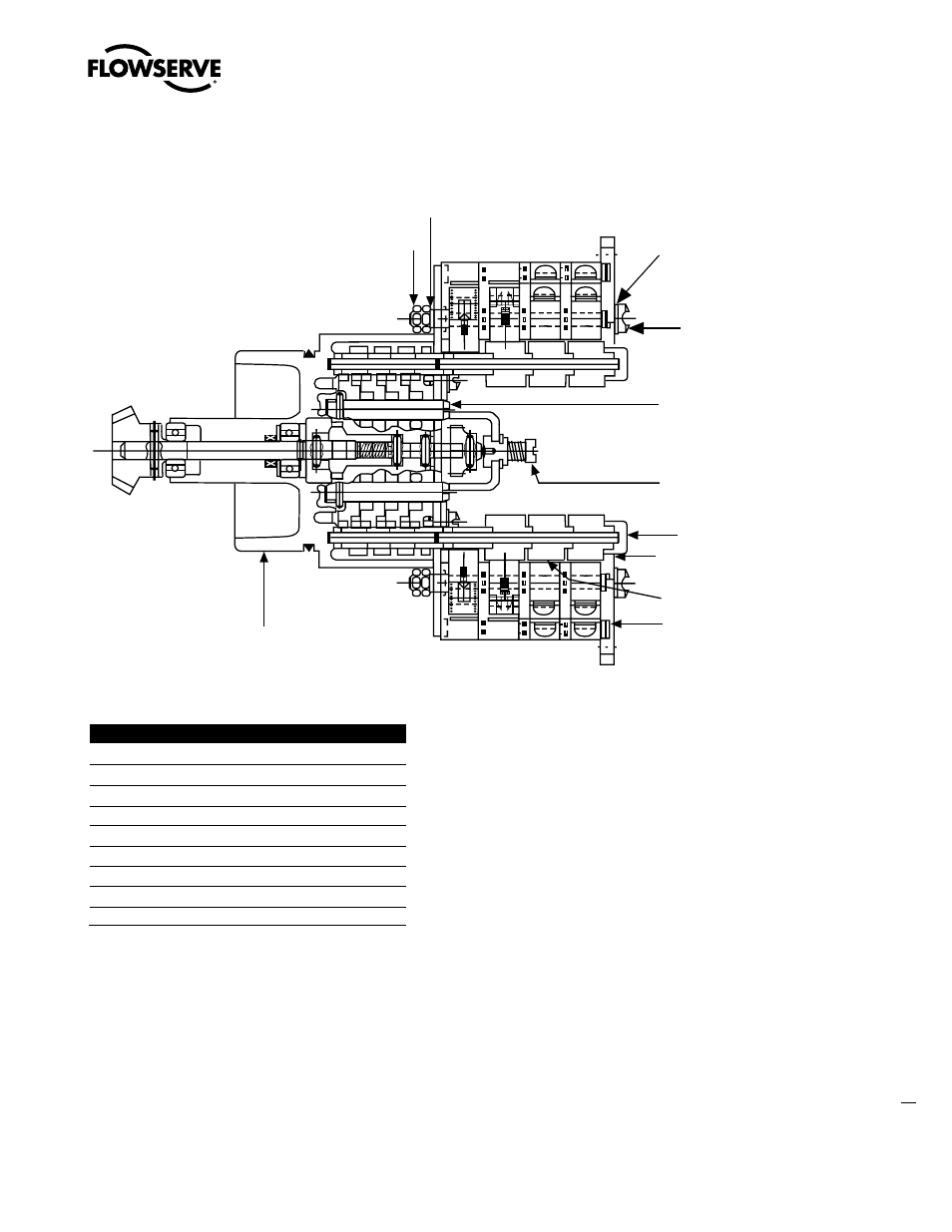
Figure 3.2 – Limit Switch
Table 3.2 – Limit Switch Parts
Piece Quantity
Description
1
1
Gear Frame Assembly
2
2
Eight-Switch Contact Block Assy.
3
12
Rotor Segment (short)
4
4
Rotor Shaft
5
4
Machine Screw
6
4
Flat Washer
7
4
Lock Washer
8
8
Hex Nut
9
4
Rotor Segments (long)
3.3.2 Setting Procedure (Refer to Figure 3.2)
1. Open the Controls Compartment Cover (refer to Figure 5.5).
2. Put the actuator into manual operation. Use the handwheel to operate the valve in the “open” direc-
tion. While operating the valve, note the direction of the Intermediate Shaft (B) corresponding to the
rotor or rotors to be set.
3. When the valve is fully open, close it one turn of the handwheel to allow for coast of moving parts
or refer to the valve manufacturer setting requirements.
4. Push in the Setting Rod (A) and turn one-quarter turn. The rod will latch in this depressed position.
1
2
9
3
4
B
A
6
5
7
8