2 balancing torque switch – Flowserve UEX Limitorque User Manual
Page 9
9
Limitorque UEX FCD LMENIM1205-03-AQ – 05/15
flowserve.com
• Installing or adjusting the torque switch with the actuator in a loaded condition will result in a loss
of torque protection.
Item letters correspond to Figure 3.1.
1. Place the L120 actuator in manual mode.
2. Release the load on the wormshaft spring pack.
3. For open and close directions, loosen Screw (A) and move Pointer (B) to desired position. A higher
number indicates a high torque and/or thrust output.
4. Tighten Screw (A).
5. Operate the valve electrically to seat valve and to ensure tight shutoff.
6. Rebalance torque switch if required.
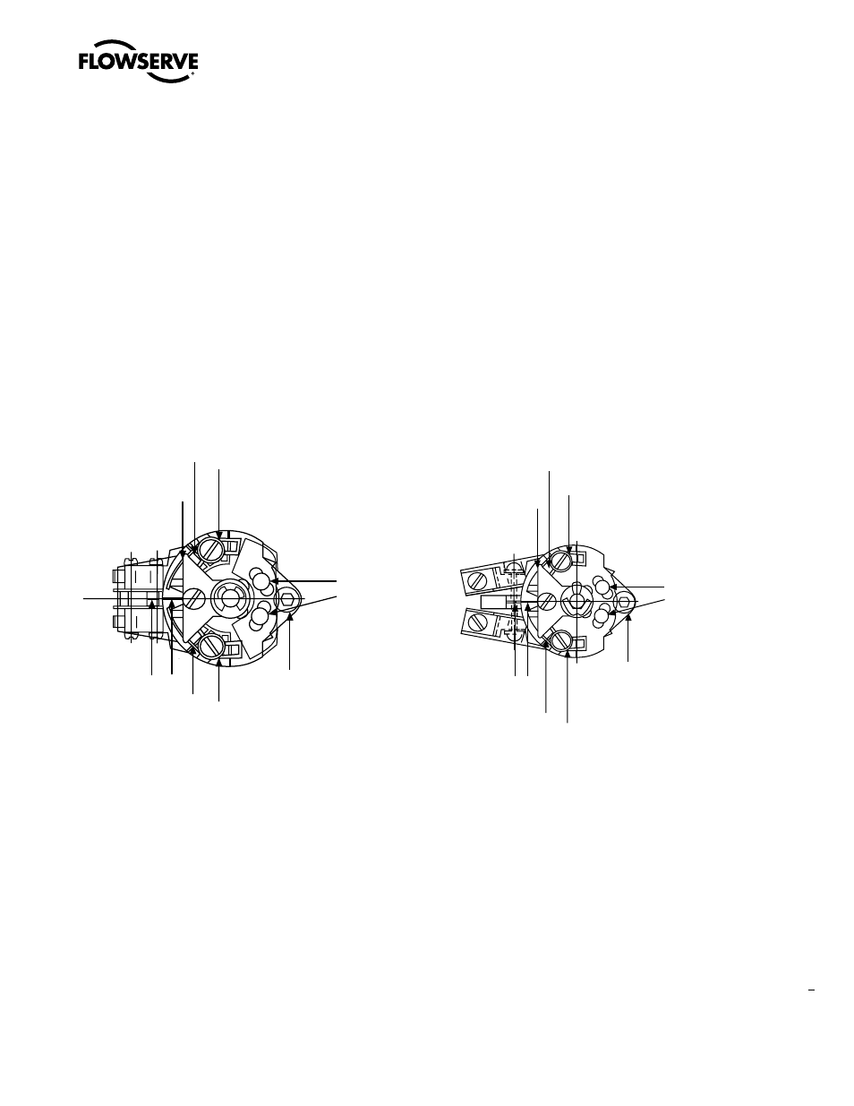
Figure 3.1 – Microswitch-Style Torque Switch and 600 Volt Torque Switch
3.2.2 Balancing Torque Switch
Item letters correspond to Figure 3.1.
1. Place the actuator in manual mode.
2. Remove the load from the wormshaft spring pack.
3. Note the open and close torque switch settings prior to reinstalling the torque switch.
4. Loosen Screws (A) and position both Pointers (B) at the #1 setting, tighten Screw (A). In this
position the index marks should be aligned.
Mounting
Screw
Index Marks
Maximum Stop
Setting Plate
A
B
Balancing
Screws
600 Volt Torque Switch
A
B
B A
B A
Microswitch-Style Torque Switch
Mounting
Screw
Index Marks
Maximum Stop
Setting Plate
Balancing
Screws
-10-20
CLOSE
OPEN
-10-20