3 combination of contacts (refer to figure 3.2) – Flowserve UEX Limitorque User Manual
Page 12
Limitorque UEX FCD LMENIM1205-03-AQ – 05/15
12
5. Refer to the applicable wiring diagram for contact development. The limit switch contact is closed
when the rotor is engaged with the plunger. If the rotor to be set has not turned 90 degrees to
operate the plunger, turn the intermediate shaft in the same direction as noted in Step 2 until the
rotor clearly trips the switches. This rotor is now set correctly.
6. Before moving the valve, depress and turn the Setting Rod (A) one-quarter turn to the spring
released position. Insert a screwdriver into the intermediate shafts to ensure that they will not move.
a
CAUTION: Do not operate the valve when Setting Rod (A) is in a fully depressed position. Loss of
contact setting will occur and the setting rod will be damaged.
7. Operate the valve by handwheel to fully “close” position; reverse direction by one turn of the hand-
wheel to allow for coast of moving parts or refer to the valve manufacturer setting requirements.
8. Set the other rotors by following Steps 4 through 6.
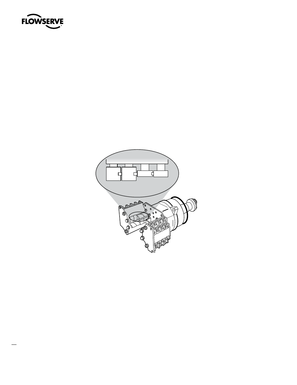
Figure 3.3 – Setting the Open and Closed Contacts
3.3.3 Combination of Contacts (Refer to Figure 3.2)
The rotor segments can be separated and rotated through 90 degrees to give various combinations of
normally open or normally closed contacts to each rotor.
1. Remove Nuts (piece 8) and Fillister Head Machine Screws (piece 5, for a total of two fasteners on
each side of the switch).
2. Remove complete contact assembly from the back plate.
3. Rearrange cams on the camshaft to produce the required combination of contacts.
4. Replace contact assembly on back-plate (ensuring that the registers fit correctly) and secure with
the machine screw and nuts.
5. Set limits according to the procedure above.
NOTE: For mechanical operation and maintenance of the L120 actuators, please see section 5 and 6 of
LMENIM1201.
Closed
position
Open
position