3 power supply – Fluke Biomedical 10100AT User Manual
Page 48
10100AT
Operators Manual
3-2
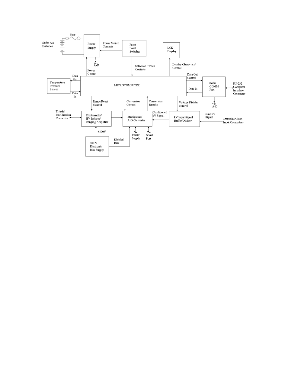
Figure 3-1.
Hardware Block Diagram of the Model 35050AT Dosimeter
3.3 Power Supply
All power for the unit is derived from either the supplied AC Adapter or 6 “AA” alkaline batteries. When
operating on battery power, the batteries will normally provide a continuous operational life of
approximately 30 hours. An automatic turn off feature will power down the unit after a period of inactivity
(no key presses or exposures are detected). This period may be set by the user during the customization
procedure (see the Model 35050AT Customization Instruction Manual for details). A low battery
annunciator is displayed when less than 2 hours of the useful battery life remains, and automatic power-
down occurs when the battery is completely exhausted. Battery voltage may be checked by scrolling
through the Options menu until the Battery Voltage is displayed.
When operating with the AC Adapter, the batteries no longer provide any power to the unit. The automatic
turn off feature is disabled when the AC adapter is in use. When checking the battery voltage, via the
Options menu, while the AC adapter is in use, the voltage displayed is the AC adapter voltage which is
approximately 12 volts. The AC adapter provided with the 35050AT is rated at 9 volts at 200mA (0.2A). It
is an unregulated adapter, and as such its output voltage displayed from the Options menu will normally
be between 10 and 13 volts. This is because the unit does not draw 200 mA from the adapter; it normally
draws approximately half as much. This causes the output voltage to rise.
An in-line fuse located within the battery compartment has been provided for safety. Fuse failure would
normally indicate a fault within the unit. The function of the power supply block is to first regulate the
battery voltage, and second to transform it to the various levels required by the system. The power
supply provides power to all of the other blocks in the system. These interconnections have been omitted
for clarity.
Although the power supply is under the control of the microcomputer during normal operation, it is forced
to turn on when the operator presses the front panel POWER ON/OFF button. The connection between
the Power Supply and the Multiplexer/A-D Converter provides the means by which the microcontroller can
monitor the battery voltage and thus detect low and exhausted batteries. This voltage is also displayed
during the power-up sequence and on one of the Test screens. Since the measurement point is not