Fluke Biomedical 10100AT User Manual
Page 71
Appendix
Radiological Specifications
C
C-3
Incident Beam Direction: For diagnostic measurements, the reference direction of incident radiation is
perpendicular to the entrance window with the “DIAGNOSTIC FOCUS” sticker attached, and with this
window facing the x-ray source. For mammographic measurements, the reference direction of incident
radiation is perpendicular to the entrance window with the “MAMMOGRAPHY FOCUS” sticker
attached, and with this window facing the x-ray source.
Angular Dependence: The ion chamber response to radiation incidence variations up to ± 8° of normal
is within ± 1% of the response to incident radiation striking perpendicular to the entrance window
surface.
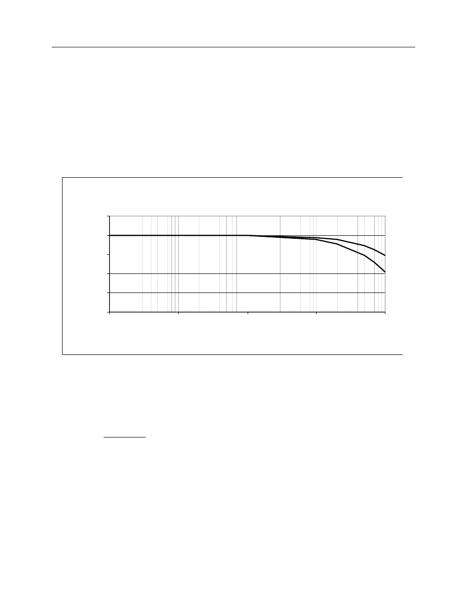
Collection Efficiency: The collection efficiency for both continuous intensity and 120 Hz half wave
rectified intensity is theoretically calculated using Boag’s equations. An ionization potential of 300V is
used in both cases. An effective plate separation distance of 0.73 cm was determined experimentally
and used to generate the curves shown in Figure C-2.
Figure C-2.
Collection Efficiency of Model 96035B Ion Chamber
Ion Transit Time: Maximum of 0.67 ms in the center of the chamber at STP with a bias voltage of 300
volts.
Air Density Correction: To perform air density corrections when using a calibration factor with a
reference temperature of 22°C, multiply the ion current by the following correction factor, F:
(273.15 + T)
F =
295.15 x P
where T is the temperature in °C, and P is the pressure expressed as a fraction of a standard
atmosphere (1013 hPa). For chambers with a calibration factor normalized to 20°C, the denominator is
293.15 x P.
Average Intensity (mGy/s)
60%
70%
80%
90%
100%
110%
1
10
100
1000
10000
Average Intensity (R/min)
Collection Efficienc
y
Continuous
Half Wave
1460
146
14.6
1.46
0.146