Fluke Biomedical 10100AT User Manual
Page 77
Appendix
Energy Correction Factors
C
C-9
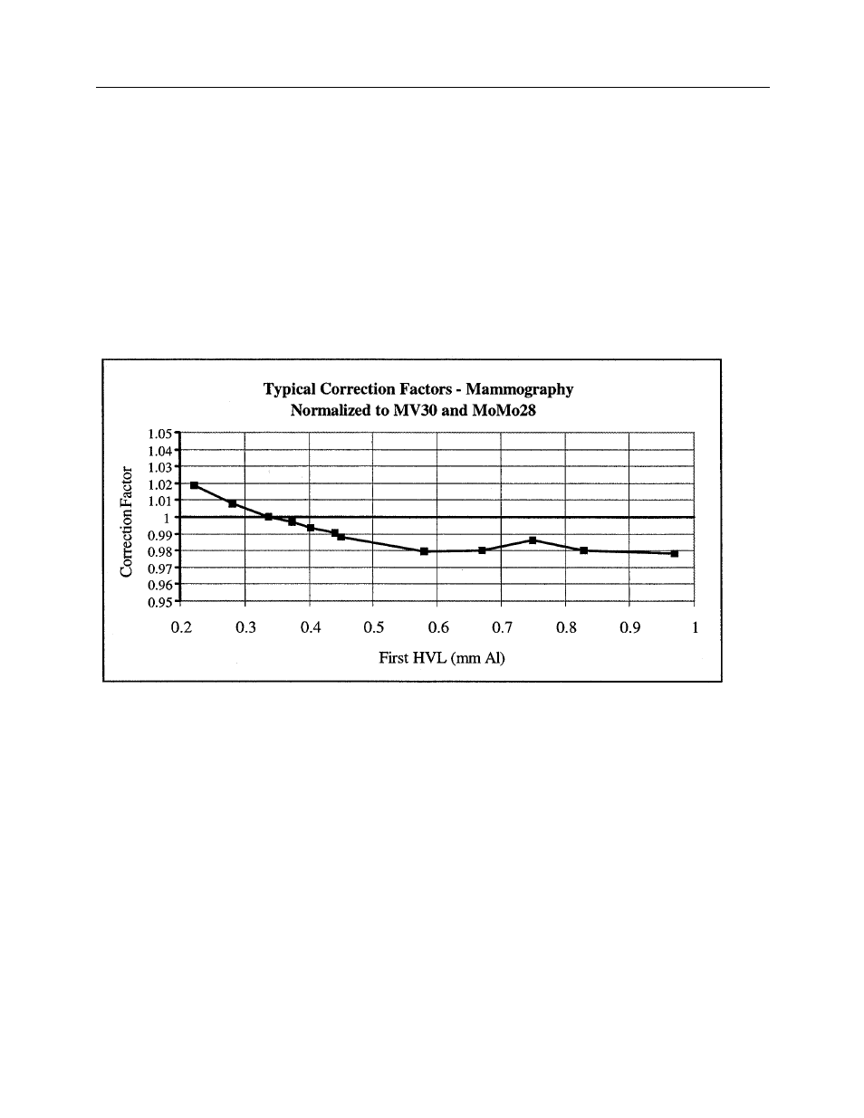
Typical energy correction factor curves are obtained by dividing the calibration factor at each beam
quality by the calibration factor at a reference point and plotting the result versus first HVL. MV30 is
chosen as the reference point for chambers receiving the standard calibration while MH30 is chosen for
chambers receiving the PTB calibration option. Since the response of the chamber at MoMo28 is
equivalent to the response at MV30, the first curve is also considered normalized to MoMo28.
The typical correction factor curves for mammography are shown below normalized to MV30 and
MoMo28 in Figure C-6 and MH30 in Figure C-7. All 96035B ion chambers must have an actual correction
factor within ± 1.5% of the value shown in the curves at any point.
The actual points plotted in the graphs below correspond to the points in the MV and MH series of beam
qualities. Users making measurements at a beam quality similar to one of the PTB mammographic
beams may easily obtain the appropriate correction factor by assuming the HVL of the most equivalent
PTB beam. For a more precise correction factor value, the user may calculate the actual first HVL and
locate the proper correction value on the curve.
Figure C-6. Energy Correction Factors for Model 96035B for Mammography Normalized to MV30 and
MoMo28