Typical data link settings – GAI-Tronics LE200-RM Rack-Mount Page/Party Line Extender User Manual
Page 25
Pub. 42004-392G
M
ODEL
LE200-RM
R
ACK
-M
OUNT
P
AGE
/P
ARTY
®
L
INE
E
XTENDER
P
AGE
23 of 56
e:\standard ioms - current release\42004 instr. manuals\42004-392g.doc
09/14
Typical Data Link Settings
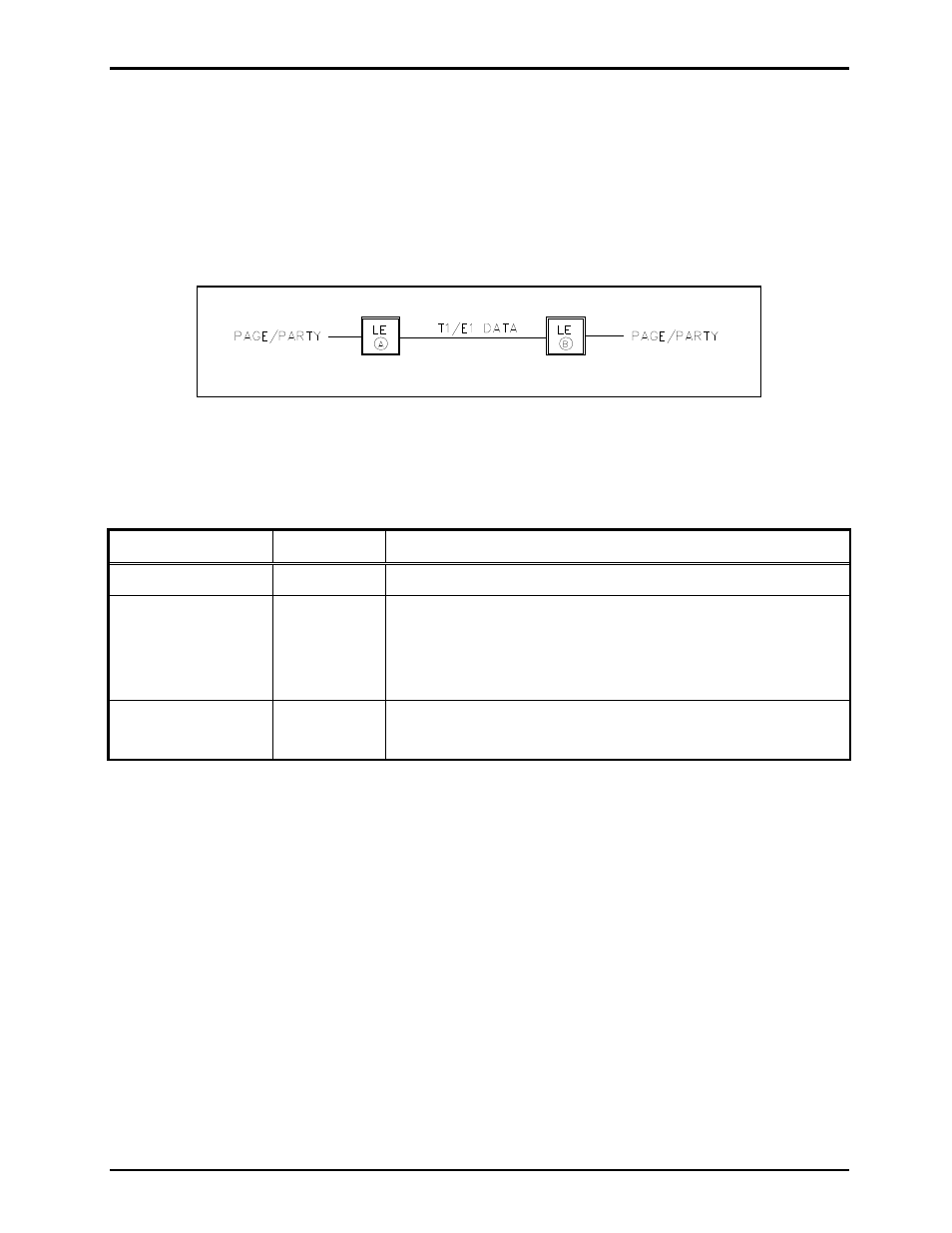
The following section shows the most common Line Extender connection schemes and the expected T1/E1
and LVDS data line parameters for each. Consult the applicable tables above to determine the correct
switch settings. Consult GAI-Tronics for technical support of connection schemes not shown in this
manual.
Point-to-Point Page/Party
®
System Connection
Figure 7. Point-to-Point Page/Party
®
System Connection
Table 24. Point-to-Point Page/Party
®
System Connection Table
Parameter Switch
Configuration
Description
T1 Line Length
SW2
Determined by installation distance between LE200-RMs.
T1/E1 Clock Source
SW3-1
SW3-2
Unit A is the master clock source:
SW3-1 (open) SW3-2 (open)
Unit B is the slave and uses the T1/E1 clock from Unit A:
SW3-1 (closed) SW3-2 (closed)
LVDS Clock Source SW3-3
SW3-4
Not used - disable both LVDS “in” and “LVDS out”:
SW3-3 (open) SW3-4 (open)