GAI-Tronics 12509-037 Telephone Management Application (TMA) Installation Bulletin (Ver. 7.3.3 and newer) User Manual
Page 10
Pub. 42004-447A
Telephone Management Application (TMA) Installation Bulletin
Page: 10 of 19
f:\standard ioms - current release\42004 instr. manuals\42004-447a.doc
04/11
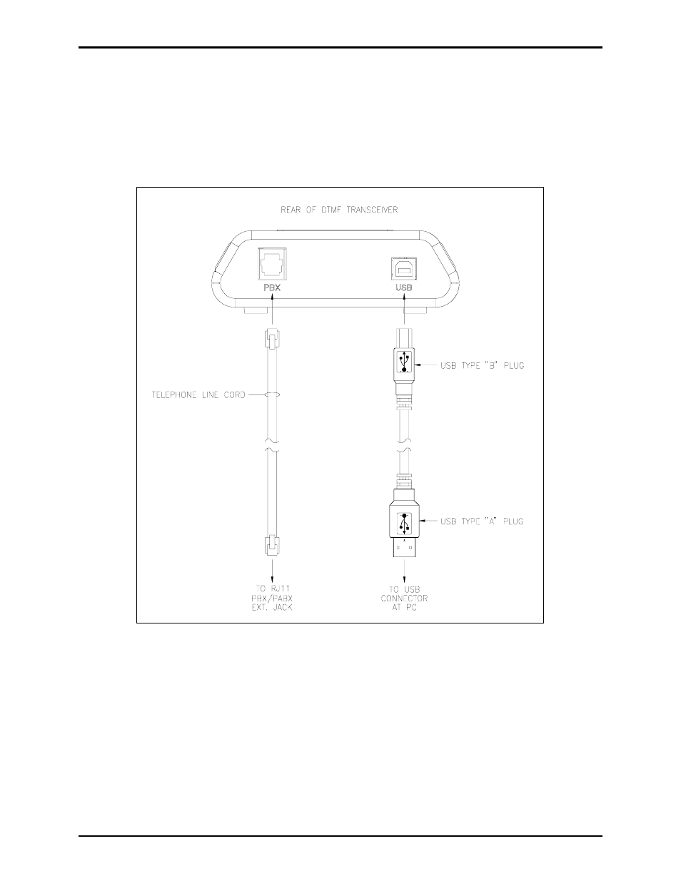
14. With the TMA software installation complete, the TMA DTMF Transceiver must be connected to the
PC and PBX/PABX extension telephone line using the USB cable and telephone line cord provided.
Refer to Figure 1 below and the following guidelines for these connections:
•
USB connection – Insert the large USB type “A” plug into a USB port at the PC, and the small
USB type “B” plug into the USB jack at the rear of the TMA DTMF Transceiver.
•
PABX telephone connection – Insert one end of the telephone line cord into the RJ11 jack at the
rear of the TMA DTMF Transceiver, and the other end into a dedicated PABX jack at the wall.
Figure 1. TMA DTMF Transceiver Connections
15. After the USB and telephone cables are connected, the TMA DTMF Transceiver OH/PWR LED
should begin to flash on and off to indicate the unit is receiving power via the USB connection.
16. Insert the USB security key into an available USB port at the PC.