Figure 5-8 – Gasboy CFN Series Site Controller III User Manual
Page 58
Advertising
Pump/Remote Dispenser Wiring
Control Lines
Page 54 MDE-4298D CFN Series Site Controller III Installation Manual · September 2009
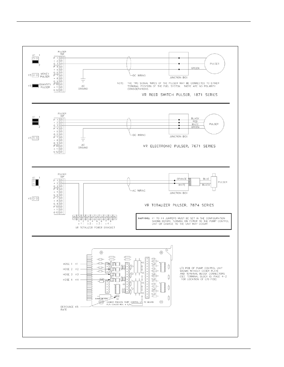
Figure 5-8: Pulser Wiring and Configuation Diagrams
Note: All pulsers shown above are connected to the hose #1 position. The K1 jumper pins are used to configure the circuitry
for hose #1. The jumper pins associated with the other hoses are indicated above.
Advertising
See also other documents in the category Gasboy Hardware:
- 216S (18 pages)
- Atlas Fuel Systems Site Prep Manual (42 pages)
- Atlas Technician Programming Quick Ref (2 pages)
- ATC M05819K00X Kits (28 pages)
- Atlas Fuel Systems Owner Manual (80 pages)
- Gilbarco Global Pumping Unit Operation Manual (42 pages)
- 26 (7 pages)
- Atlas Valve Replacement Kits (10 pages)
- Atlas Fuel Systems Installation Manual (100 pages)
- 9820K (6 pages)
- 9120K (8 pages)
- Atlas Single Std. Inlet Centering Kit (8 pages)
- 8800 Atlas (1 page)
- 9120K Series Service Manual (40 pages)
- 9800A Atlas (6 pages)
- 9800 Atlas (20 pages)
- 9800 Atlas (14 pages)
- M08400 (6 pages)
- 9100 Series (8 pages)
- 9820K Series Installation (62 pages)
- 9853K (8 pages)
- 9216KTW (36 pages)
- Recommended Spare Atlas (14 pages)
- DEF Atlas (28 pages)
- 9820K Series (12 pages)
- 9800Q (1 page)
- Q Series (3 pages)
- 8753E (2 pages)
- 9152AXTW2 (1 page)
- 8800E (1 page)
- 8800E (2 pages)
- 9820Q Series (1 page)
- Atlas Start-up (230 pages)
- 9800A (4 pages)
- 9820A (1 page)
- 2600A (3 pages)
- 2600A (12 pages)
- 2600A (2 pages)
- 9800Q Front Load Vapor (2 pages)
- 215A (1 page)
- 9800Q Vapor (2 pages)
- 216A (31 pages)
- 215A (2 pages)
- Lamp Kit (2 pages)
- 9120Q Pulser (1 page)