Hardware, Control device, Part iii hardware – Geist R-Series PDU v4 User Manual
Page 14: 3hardware, 1 control device
R-Series PDU v4 Instruction Manual
14
© 2014 Geist
3
Hardware
3.1
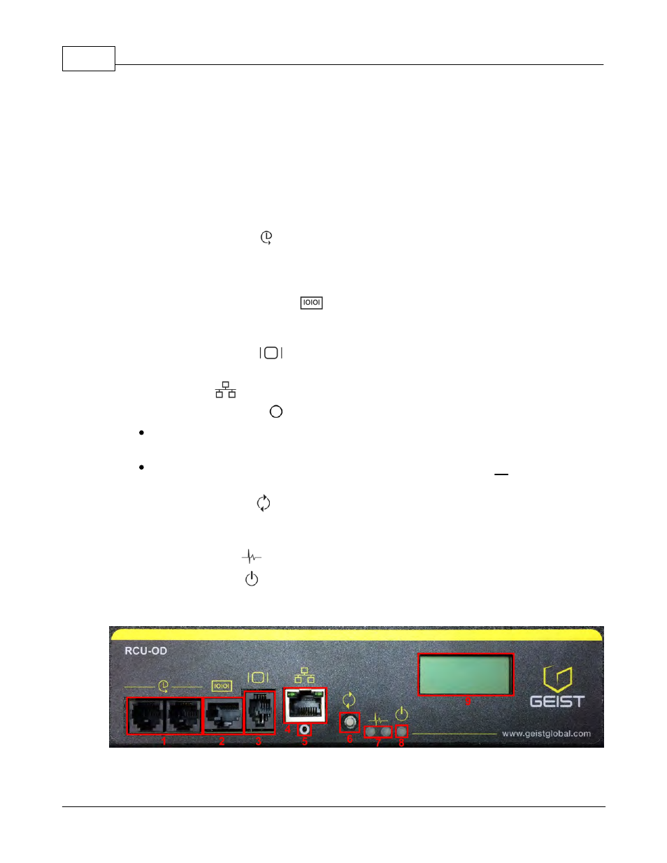
Control Device
The R-Series PDUs have an advanced feature set for data centers that need full
remote monitoring, logging and alarms with options for outlet level monitoring and
switching control. The PDU supports multiple I/O options.
1.
Remote Sensor Port ( ): Two RJ12 ports for connecting Geist plug-and-play
remote sensors (sold separately). Splitters may be used to add additional sensors.
Each sensor has a unique serial number and is automatically discovered. R-
Series PDUs support up to sixteen sensors.
2. Serial Communication Port (
): The R-Series PDUs provide an out-of-band,
serial monitoring interface. The unit provides a RJ-45 port for RS-232 serial
communication, providing support for Telnet and SSH via command line.
3. Remote Display Port (
): An optional remote display (RSD2X8) can be
connected to the R-Series PDU.
4. Ethernet Port (
): RJ45 port for connecting the PDU to a TCP/IP network.
5. Network-Reset Button (
):
Holding the network-reset button for 15 seconds during normal operation will
restore the default IP address and reset the user accounts.
Holding the network-reset button during power-up will reset all of the unit's
settings back to factory-default values.
6. Hard-Reboot Button (
): Pressing the hard-reboot button reboots the monitoring
device. This acts as a power-cycle for the device, and does not change or remove
any user information. Note: This will NOT affect power to the connected devices.
7. Activity/Idle LEDs (
)
8. Power Status LED (
)
9. Local LCD Display: The local display scrolls through the values of the
measurements selected on the LCD Display page.
For R-Series Switched PDUs, there is an LED next to each outlet providing feedback
for the current state.