Phase 3: inspect the cable and sensor, Some tips, Items needed – Infloor Standard Electric Cable User Manual
Page 5: Always step 3.1 step 3.2
Infloor Installation Manual
5
AL WAYS completely embed the heating wire and factory splices in the floor mortar .
AL WAYS maintain a minimum of 2” spacing between heating wires .
AL WAYS pay close attention to voltage and amperage requirements of the breaker,
the thermostat, and the heating wire. For instance, do not supply 240 VAC power
to 120 VAC wire as damage will result.
AL WAYS make sure all electrical work is done by qualified persons in accordance
with local building and electrical codes, Section 62 of the Canadian Electrical Code
(CEC) Part I, and the National Electrical Code (NEC), especially Article 424 .
AL WAYS use copper only as supply conductors to the thermostat . Do not use alumi-
num .
AL WAYS seek help if a problem arises . If ever in doubt about the correct installation
procedure to follow, or if the product appears to be damaged, the factory must be
called before proceeding with the installation .
Some Tips
Trowel. Use a plastic trowel to reduce the possibility of cable damage .
Insulation. The better insulation that is provided, the more efficiently
the system operates, and the better the floor is heated . Concrete slab sur-
faces offer the most thermal drain and should be insulated before applying
the cables, if at all possible . See “Phase 9: Install Insulation” as well as the
cross sections in Appendix 1 .
Controls. The Infloor controls will provide direct floor-warming control
for better comfort . Other controls are not approved for use with Infloor
Cables .
Mortars. Self-leveling mortars are becoming more popular to use
because of their ease of application over the cables . If laying tile, another
layer of thin-set will need to be applied in order to lay the tile . Always
use polymer-modified cement-based mortar . Do not use solvent-based
adhesives or pre-mixes because they are not as heat resistant .
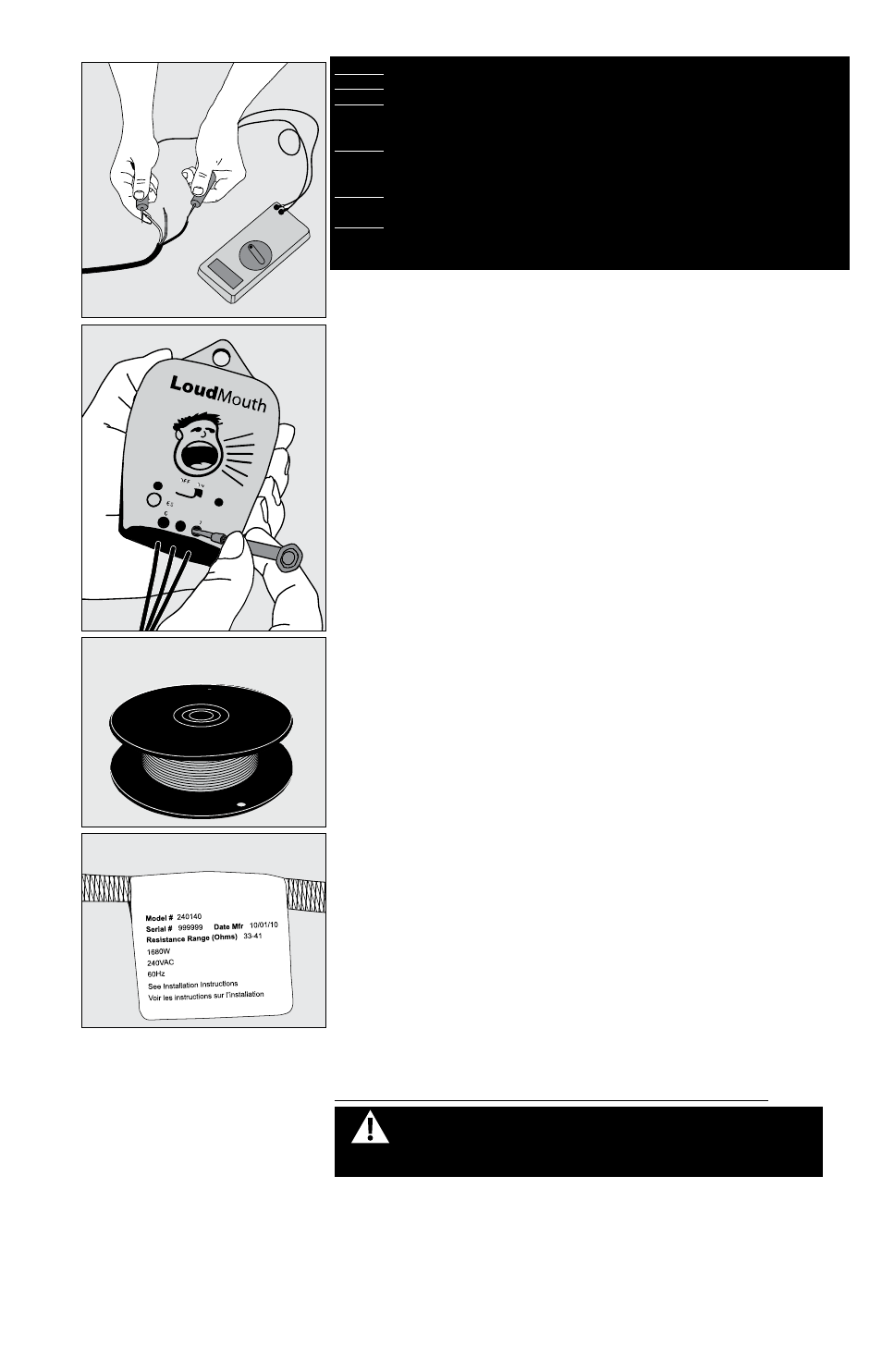
LoudMouth
™
. The LoudMouth sounds an alarm if damage occurs to
the cable during installation . The LoudMouth stays connected to the power
leads throughout cable and tile installation . A small screwdriver for con-
necting the leads is included with the LoudMouth monitor .
Items Needed
Materials:
• Infloor Electric Cable system
• Strapping (provided with cable)
• Thermostat control with floor sensor
• 20-amp circuit breaker (single for 120-VAC and dual for 240-VAC
systems)
• Electrical box (extra deep) for the control; single-gang (not a gangable
type) or 4”-square deep box with a single-gang “mud ring” cover
• 4” junction box with a cover, if needed
• Cable clamps for junction box (for new construction)
• Flexible or rigid conduit (for new construction)
• Infloor Sensor Tube p/n 29011
• 12-gauge or 14-gauge electrical wiring cable (consult local code)
• Wire nuts if using a junction box
• Nail plate
• Polymer-modified cement based mortar
Tools:
• Digital multi-meter [for ohms testing; must read up to 20,000 ohms (Ω)
to measure sensor]
• Drill with 1/2” bit
• Hammer and chisel
• Wire strippers
• Phillips screwdriver
• Fish tape (for existing construction)
• Hole saw (for existing construction)
• Trowel (plastic preferred) with 3/8” notches (or greater)
Phase 3: Inspect the Cable and Sensor
STEP 3.1 Take the cable out of the box and inspect it to make sure
there is no visible damage. Verify everything is the correct size and type
according to the plan and the order . Do not attempt to install a damaged
product .
STEP 3.2 Record the product information . There is a factory-applied
nameplate label on the power leads . Do not remove this label . Record the
cable serial number, model number, voltage, and cable resistance range in
the Cable and Sensor Resistance Log (Table 4) . If installing more than one
cable, do this for each of them .
ALWAYS
STEP 3.1
STEP 3.2
WARNING: To prevent the risk of personal injury and/or death, make
sure power is not applied to the product until it is fully installed and
ready for final testing. All work must be done with power turned off
to the circuit being worked on.