Phase 4: electrical rough-in, 7step 4.2, Step 4.5 – Infloor Standard Electric Cable User Manual
Page 7: New construction, Existing construction
Infloor Installation Manual
7
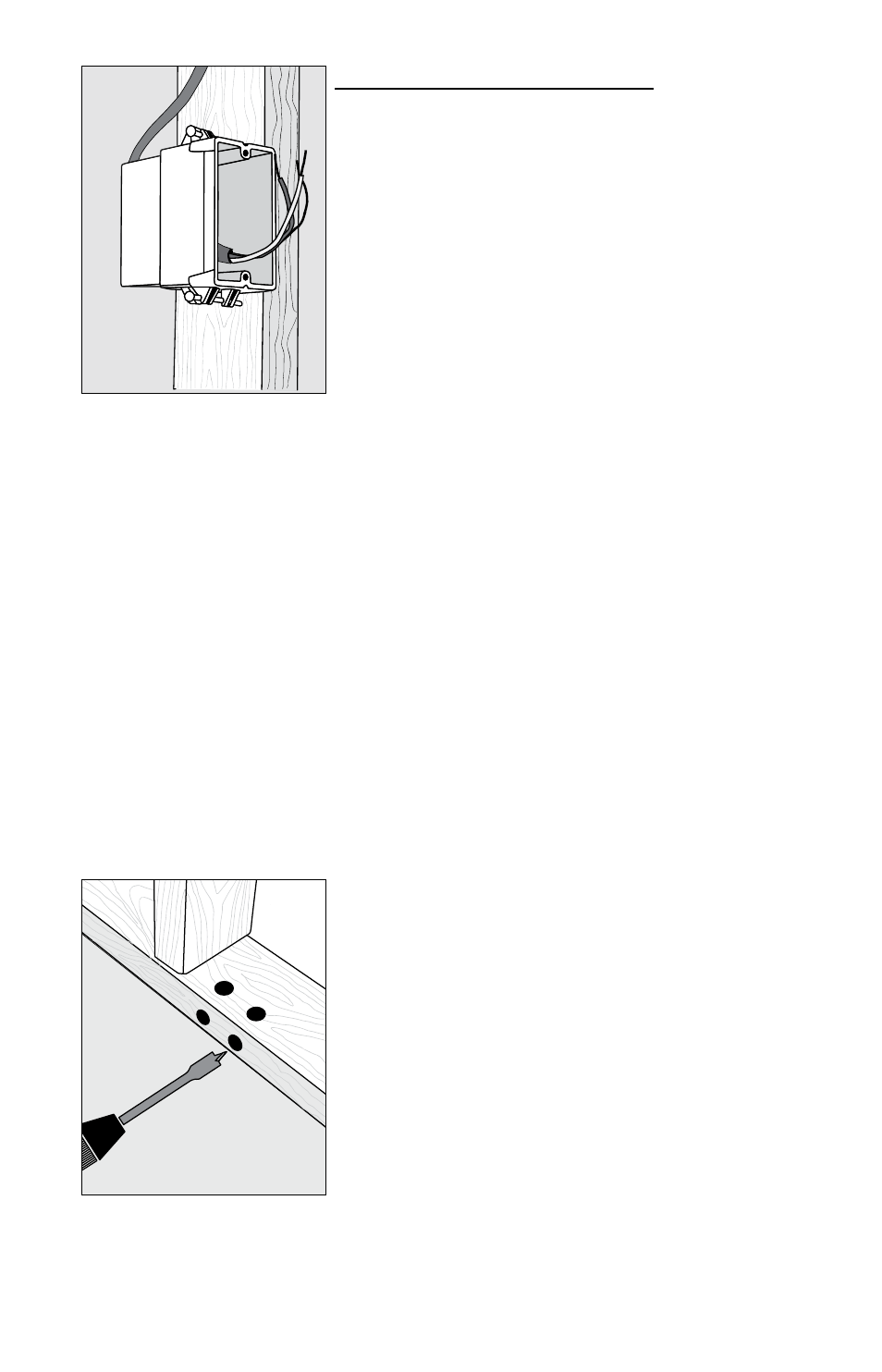
STEP 4.2
Install an extra-deep single-gang
box if connecting one or two cables
to the control . Use a 4”-square deep
box with a single-gang mud ring
cover if connecting three cables,
because the extra room is needed
for the wire, wire nuts, and control .
STEP 4.5
Phase 4: Electrical Rough-in
See wiring diagrams in Appendix 2 for different voltages and applications .
For additional help see www.infloor.com .
New Construction
(see below for existing construction)
OVERVIEW We recommend the floor-warming system be installed on a
dedicated circuit coming directly from the circuit breaker panel . Follow
all National Electric Code (NEC), Canadian Electrical Code (CEC), and other
local electrical code requirements when installing this system . Work
should be done with great care and with the power turned off to the
circuit being worked on.
STEP 4.1 Install a maximum 20-amp circuit breaker(s) into the breaker
panel, depending on the load of the system. Use a 120-VAC single-pole
breaker for a 120-VAC system. Use a 240-VAC double-pole breaker for a 240-
VAC system.
For systems that are too large to directly power through one control
but must be operated by one floor-sensing control, use a Infloor control in
combination with up to 10 Infloor Relay Controls . Contact the dealer or the
factory for more information .
STEP 4.2 Install an electrical box for the control . If installing one to two
cables, use an extra-deep single-gang box to allow plenty of room for the
wiring . Use a 4”-square box if installing three cables . The box can be located
almost anywhere that is well ventilated . However, the best place is in the
same room as the cable, typically about 60” above the floor, and within
reach of the power lead wires of the cable . If installing more than three
cables, it will be necessary to connect their power leads in a junction box
first (see Step 4 .4) to keep from overfilling the control electrical box . Then
route one power supply from this junction box to the control box .
See Step 5 .22 for special requirements if the control will connect to a
heating cable entering a shower area .
STEP 4.3 Following code, feed 14- or 12-gauge NM type electrical wiring
from the circuit breaker panel to the control electrical box . Leave about
6”–8” of extra wire extended from the box to work with .
STEP 4.4 If the control box must be mounted in a location that is too far
to reach with the power lead wires, it will be necessary to mount a junction
box where the lead wires can be terminated . Use a standard junction box
with a cover, mounting it below the floor, in the attic, or in another easily
accessible location . It must remain easily accessible and not located behind
a wall, cabinet, or similar obstruction . Then use 14- or 12-gauge NM type or
other accepted electrical wiring to connect from the junction box to the
control box .
STEP 4.5 Drill two 1/2” holes in the baseplate directly below the control
electrical box . Then, as close to the floor surface as possible, drill two
horizontal holes, intersecting the top holes .
STEP 4.6 If conduit is required by local electrical code, cut a length of
1/2” to 3/4” electrical conduit to run from the control box down to the base-
plate . At the baseplate it may be necessary to chisel out more of the wood
to make it easier to feed the wires up through the conduit .
STEP 4.7 Mark the circuit breaker in the panel which feeds the system
with “Floor warming/bath” or similar description .
Existing Construction
OVERVIEW It is recommended that the system be installed on a separate,
dedicated circuit coming directly from the breaker panel . In existing con-
struction, however, it may be difficult to do this depending on the location
of wiring and the breaker panel . Tapping off an existing circuit may be pos-
sible, but only if there is enough load capacity to handle both the system
and any additional loads that may be placed on the circuit . Keep in mind
that typical hair dryers can pull up to 10 amps (1200 watts) of load .
Follow all NEC, CEC, and other local electrical code requirements when
installing this system . Work should be done with great care and with the
power turned off to the circuit being worked on.