Rear panel, Monitor out, Surr – Marantz SR9600N User Manual
Page 12: Surr. right right surr. surr. left left, Center, Ccb b, Ppb b c cr r, Ppr r y y, Tuner-1, Lr r c c
8
ENGLISH
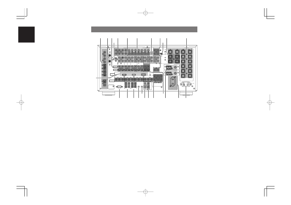
t 7.1 CHANNEL or AUX2 INPUT
By connecting a DVD Audio player, Super Audio
CD multichannel player, or other components that
has a multichannel port, you can play back the
audio with 5.1 channel or 7.1 channel outputs.
y Preamp Outputs
(L, R, SL, SR, SBL, SBR, C)
Jacks for L (front left), R (front right), C (Center), SL
(surround left), SR (surround right), SBL (surround
back left) and SBR (surround back right).
Use these jacks for connecting to external power
amplifiers.
u Main amplifier inputs
(L, R, SL, SR, SBL, SBR, C)
When the jumper plugs that link the preamp
outputs with these inputs are removed, these jacks
may be used to connect an external source to the
internal amplifiers.
Notes:
• When connecting equipment, remove the attached
jumper plugs and store them carefully so as not to
lose them.
• Only remove the jumper plugs when required.
After you finish using an main amp input jack,
replace the jumper plug.
i Subwoofer output
Connect this jack to the line level input of a powered
subwoofer.
If an external subwoofer amplifier is used, connect
this jack to the subwoofer amplifier input.
If you are using two subwoofers, either powered or
with a 2 channel subwoofer amplifier, connect a “Y”
connector to the subwoofer output jack and run one
cable from it to each subwoofer amplifier.
o Multiroom outputs (Audio L&R, Video)
These are the audio and video output jacks for the
multiroom A and B systems.
Connect these jacks to optional audio power
amplifiers or video display devices to listen and
view the source selected by the multiroom A and B
systems in a remote room.
!0 SPEAKER C switch
Set to ON to connect a bi-amp to this receiver or set
to OFF for normal speaker connection (surround
back and multiroom speakers).
(See page 27)
e VIDEO IN/OUT (DVD, LD, TV, DSS, VCR1,
VCR2/DVD-R)
These are the video inputs and outputs.
There are 6 video inputs, and 2 video outputs with
both composite video and S-video jack for each.
Connect VCRs, DVD players, and other video
components to the video inputs.
The 2 video output channels can be used to connect
VCRs for making recordings.
r AUDIO IN/OUT (DVD, LD, TV, CD, DSS,
VCR1, VCR2/DVD-R, TAPE, CD-R/MD, CD)
These are the analog audio inputs and outputs.
There are 9 audio inputs (6 of which are linked to
video inputs) and 4 audio outputs (2 of which are
linked to video outputs). The audio jacks are
labeled for cassette tape decks, CD players, DVD
players, etc. The audio inputs and outputs require
RCA connectors.
q DIGITAL INPUT (Dig. 1 - 8)/
OUTPUT (coaxial, optical)
These are the digital audio inputs and outputs.
There are 4 digital inputs with coaxial jacks, and 4
with optical jacks.
The inputs accept digital audio signals from a CD,
LD, DVD, or other digital source component.
For digital output, there is 1 coaxial output and 1
optical output.
The digital outputs can be connected to MD
recorders, CD recorders, DAT decks, or other
similar components.
w i.LINK connector
Up to S400 (400 Mbps) i.LINK devices can be
connected to this receiver.
USB AUDIO
USB AUDIO
OUTPUT
OUTPUT
INPUT
INPUT-
-1
1
(DVD)
(DVD)
INPUT
INPUT--2
2 ((DSS
DSS))
INPUT
INPUT--1
1 ((DVD
DVD))
INPUT
INPUT--3
3 ((VCR-1
VCR-1))
2
2
CD
CD
INPUT
INPUT-
-2
2
(DSS)
(DSS)
2
2
1
1
1
1
2
2
3
3
4
4
4
4
3
3
RS232C
RS232C
DC OUT
DC OUT
EMITTER OUT
EMITTER OUT
MULTI RC
MULTI RC
RC
RC-
-5
5
MONITOR OUT
MONITOR OUT
1
1
OUT
OUT
IN
IN
OUT
OUT
IN
IN
DSS
DSS
TV
TV
DVD
DVD
LD
LD
TAPE
TAPE
VCR-1
VCR-1
OUTPUT-2
OUTPUT-2
OUTPUT-1
OUTPUT-1
IN
IN
MAIN IN
MAIN IN
7.1CH IN
7.1CH IN
MULTI OUT
MULTI OUT
SURR.
SURR.
RIGHT
RIGHT
SURR.
SURR.
LEFT
LEFT
SPEAKER SYSTEMS
SPEAKER SYSTEMS
FRONT A OR B, CENTER, SURR,
FRONT A OR B, CENTER, SURR,
SURR BACK
SURR BACK : MINIMUM 6 OHMS
: MINIMUM 6 OHMS
FRONT A
FRONT A +
+ B
B : MINIMUM 8 OHMS
: MINIMUM 8 OHMS
CENTER
CENTER
FRONT B
FRONT B
RIGHT
RIGHT
FRONT B
FRONT B
LEFT
LEFT
FRONT A
FRONT A
RIGHT
RIGHT
FRONT A
FRONT A
LEFT
LEFT
SL
SL
SBL
SBL
SL
SL
SR
SR
SBL
SBL
SBR
SBR
SW
SW
A
A
B
B
SBR
SBR
SR
SR
COAX
COAX
OPT
OPT
8
8
7
7
6
6
2
2
5
5
4
4
3
3
1
1
DIGITAL
DIGITAL
IN
IN
DIGITAL
DIGITAL
OUT
OUT
OUT
OUT
AC IN
AC IN
C
CB
B
//
P
PB
B
C
CR
R
//
P
PR
R
Y
Y
C
CB
B
//
P
PB
B
C
CR
R
//
P
PR
R
Y
Y
C
CB
B
//
P
PB
B
C
CR
R
//
P
PR
R
Y
Y
C
CB
B
//
P
PB
B
C
CR
R
//
P
PR
R
Y
Y
C
CB
B
//
P
PB
B
C
CR
R
//
P
PR
R
Y
Y
R
R
L
L
MODEL NO. SR9600
MODEL NO. SR9600
TUNER-1
TUNER-1
FM(75
FM(75
Ω
Ω
)
)
GND
GND
AM
AM
FM(75
FM(75
Ω
Ω
)
)
GND
GND
AM
AM
TUNER-2
TUNER-2
((AUDIO
AUDIO))
S400
S400
S400
S400
INPUT
INPUT--4
4 ((VCR-2
VCR-2 // DVD-R
DVD-R))
VCR-2
VCR-2 // DVD-R
DVD-R
IN
IN CD-R
CD-R // MD
MD OUT
OUT
R
R
L
L
(
(AUX 2
AUX 2)
)
C
C
AUDIO
AUDIO
PRE OUT
PRE OUT
L
L
R
R
C
C
AUDIO
AUDIO
SW
SW
VIDEO
VIDEO
S-VIDEO
S-VIDEO
R
R
L
L
MULTI OUT
MULTI OUT
VIDEO
VIDEO
A
A
B
B
COMPONENT
COMPONENT
VIDEO
VIDEO
HDMI
HDMI
Ver 1.1
Ver 1.1
FLASHER
FLASHER RECEIVER
RECEIVER
IN
IN
IN
IN
IR
IR
OUT
OUT
IN
IN
SURR.BACK
SURR.BACK
/MULTI SPK.
/MULTI SPK.
/SPK. C
/SPK. C
RIGHT
RIGHT
SURR.BACK
SURR.BACK
/MULTI SPK.
/MULTI SPK.
/SPK. C
/SPK. C
LEFT
LEFT
ON
ON
OFF
OFF
SPEAKER C
SPEAKER C
UNSWITCHED 100W MAX
UNSWITCHED 100W MAX
AC OUTLET
AC OUTLET
230V 50/60H
230V 50/60H
Z
Z
q w
y
o !1
t
u
i
!2
e
r
!3
!7
!8
@2
@3
@4
!9
@1
!4
!5
@0
@5
!6
!0
REAR PANEL
¡5
SIGNAL FORMAT indicators
2
SURROUND
This indicator is illuminated when a Dolby
Surround signal is input.
MATRIX
This indicator is illuminated when a Matrix 6.1
Surround signal is input.
DISCRETE
This indicator is illuminated when a Discrete ES +
Discrete 6.1 Surround signal is input.
DUAL MONO
This indicator is illuminated when a Dolby Digital or
DTS dual mono signal is input.
NO AUDIO
This indicator is illuminated when the input signal
is PCM NO AUDIO.
¡6
ENCODED CHANNEL STATUS indicators
These indicators display the channels that are
encoded with a digital input signal.
If the selected digital input signal is Dolby Digital
5.1 ch or DTS 5.1 ch, “
L
”, “
C
”, “
R
”, “
SL
”, “
SR
” and
“
LFE
” will be illuminated.
If the digital input signal is 2 channel PCM-audio,
“
L
” and “
R
” will be displayed. If Dolby Digital 5.1 ch
signal with a Surround EX flag or DTS-ES signal
comes in, “
L
”, “
C
”, “
R
”, “
SL
”, “
S
” , “
SR
” and “
LFE
”
will be illuminated.
When playing back a disk such as an SA-CD or
DVD-Audio disk, the actual audio and display may
not match with some DVD players.
¡7
VOLUME indicator
The volume level is indicated as a bar graph and
numerically in decibels.
¡8
HDMI / HDMI THR indicator
HDMI
This indicator is illuminated when HDMI AUDIO is
s e t t o “
E N A B L E
” a n d a n H D M I d e v i c e i s
connected to the SR9600.
HDMI THR
This indicator is illuminated when HDMI AUDIO is
set to “
THROUGH
” and an HDMI device is
connected to the SR9600.(See page 44)
SR9600N DFU_01_ENG 1_4
05.5.23, 5:40 PM
Page 8
Adobe PageMaker 6.5J/PPC