Block diagrams, Figure 8: rt-3010 block diagram – NavCom RT-3010 Rev.F User Manual
Page 43
RT-3010 User Guide – Rev. F
9 Most antenna’s have better gain when the satellite
is high in elevation. Expect tracking performance
to fade as the satellite lowers in elevation. It is not
unusual to see 10dB difference in antenna gain
(which translates into signal strength) throughout
the entire elevation tracking path.
9 Map obstructions above the horizon using a
compass and inclinometer. Use satellite prediction
software with a recent satellite almanac to assess
the impact on satellite visibility at that location
(available on NavCom’s web site).
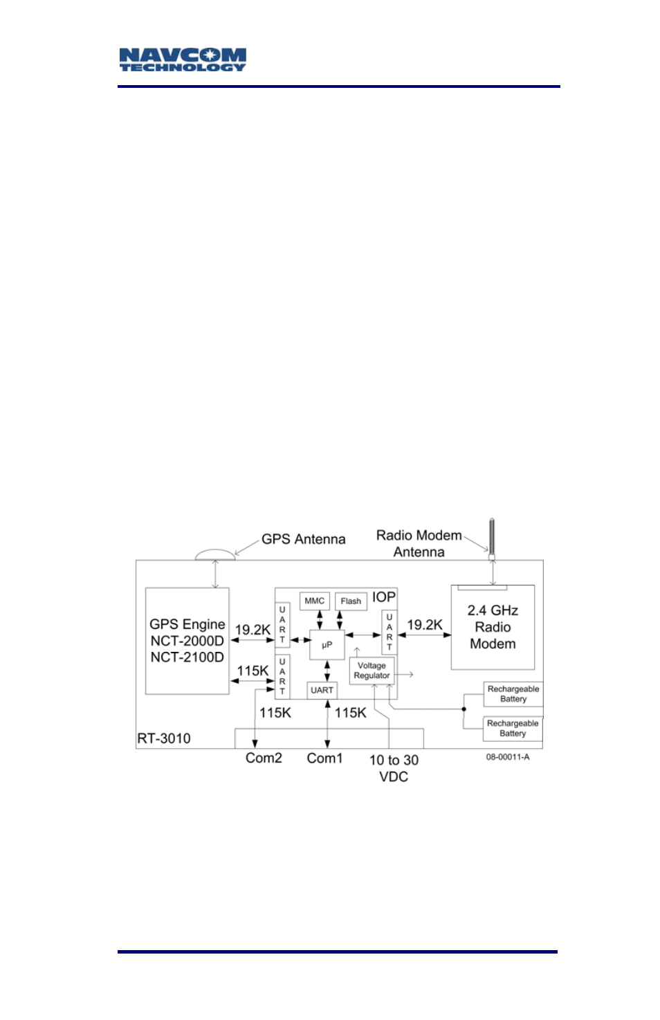
Block Diagrams
The RT-3010 has three user configurable physical
communications ports (two external and one internal)
and several logical communications ports. To aid in
distinguishing these ports, please refer to the block
diagram below.
Figure 8: RT-3010 Block Diagram
These user configurable physical ports
are Com1, Com2, and Radio/Diagnostic.
The Com ports are described in the next
section.
3-41