NIStune Type 4 User Manual
Page 6
Type 4 Hardware Installation Manual
Page 5 of 21
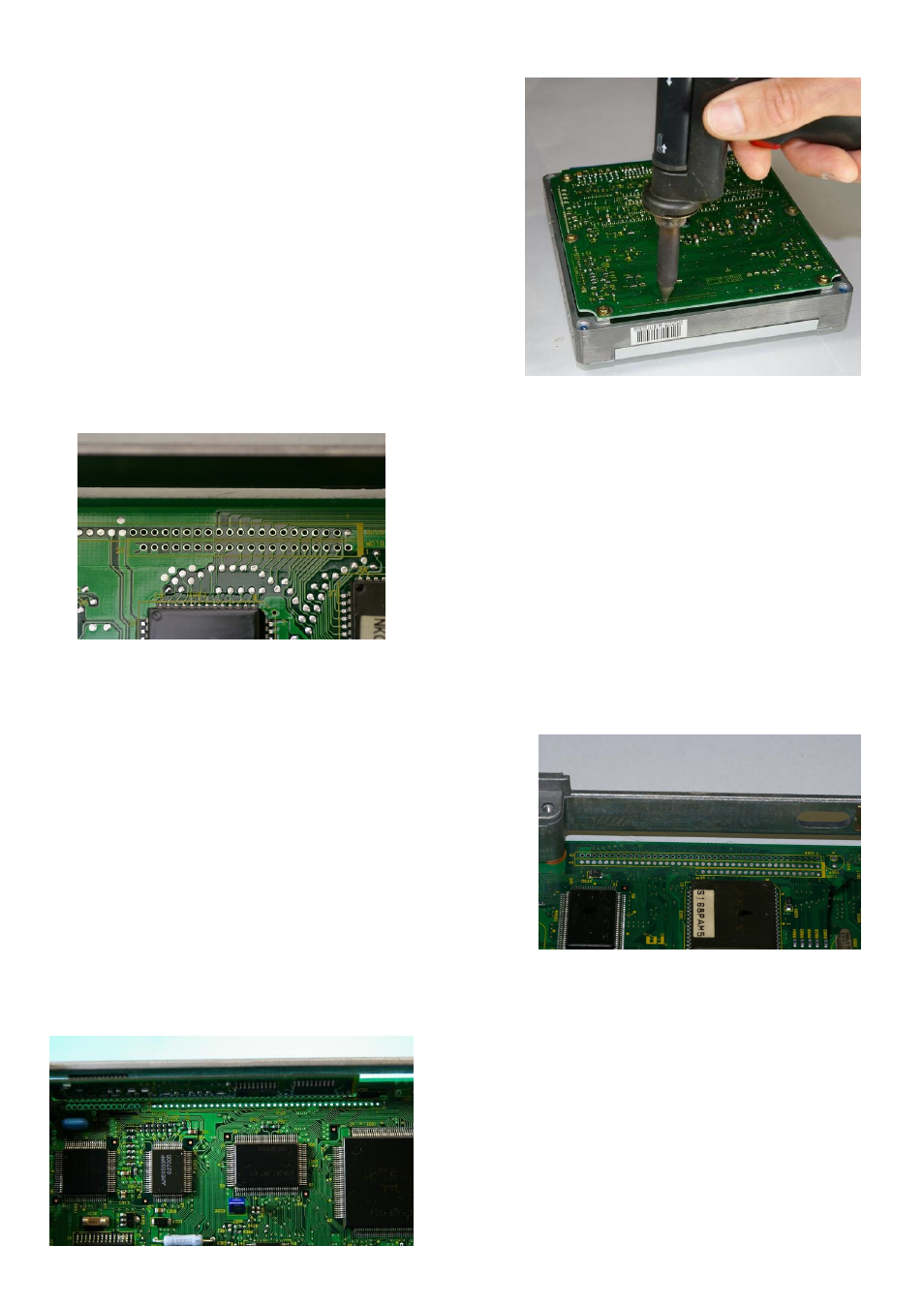
• Solder removal
Using a de-soldering gun with a small tip carefully
remove the solder for the connector matching your
ECU type. This is best performed from the rear of the
board.
Adaptor A
SR20DET from Late S13 180SX, S14A & S15, UK N15
Almera GTi, P11 Primera, Late W10 Avenir, Late K11
Micra 98-02.
On W010 (20 pads) de-solder pads 1 - 20
On W020 (30 pads) de-solder pads 2 – 21
Note the 1 pad offset between the two rows
.
Adaptor B
S14 KA24DE/U13 KA24DE/N15 GA16DE/B14
SR20DE/A32 VQ30DE/Z32 VG30DETT 1996 -
De-
solder the W001 row of pads 1 - 40 (outside row).
Y33 VQ30
– de-solder W010 pads 1 - 40 (no photo
currently available).
Adaptor C
ER34 RB25DET / WC34 RB25DET (series 2)
De-solder the W100 row of pads 1 - 40 (inside row)
Autos will have the outside row of pads already used by a
board containing auto control circuitry, as shown in this
photo. You may need to carefully bend this board towards
the ECU wall to obtain clearance.
Pads de-soldered for Adaptor A
Pads de-soldered for Adaptor B
Pads de-soldered for Adaptor C