Vav/cav controller setpoints, Vav/cav confi guration screens – Orion System VAV II Controller v.1 User Manual
Page 29
VAV/CAV/MUA Operator Interface SD
VAV/CAV CONTROLLER SETPOINTS
29
Confi guration Screens #22-41 - Relay
Confi guration Screens
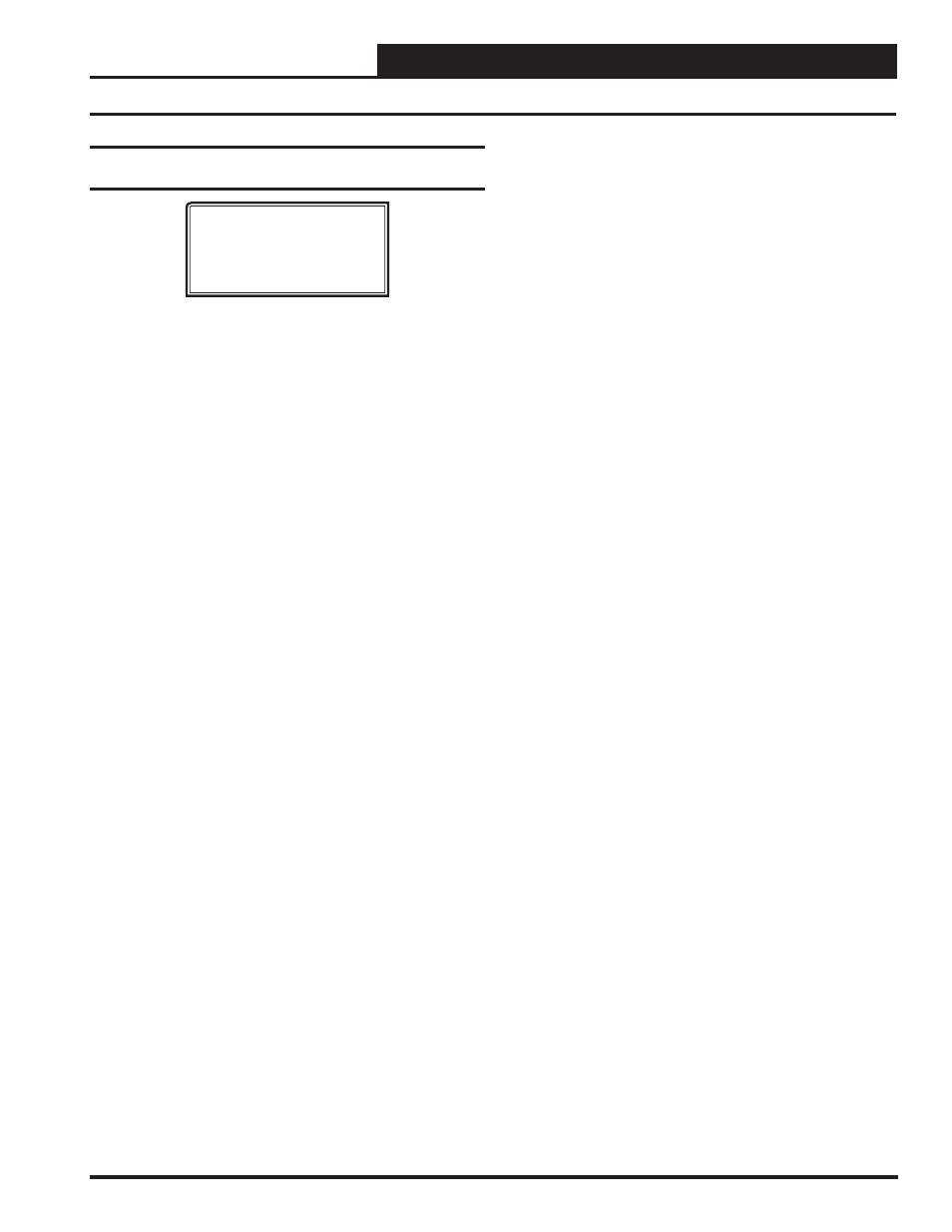
VAV/CAV Cnfg ID 0001
Relay Configurations
Rly xx: Not Used
Use < Or > To Change
The 20 Relay screens allow you to set the 4 relays on the VAV/CAV
Controller and up to 16 additional relays when relay expansion board(s)
are used.
The fi rst relay on the VAV/CAV Controller is always reserved for the
Supply Fan. Relays #2 through #21 can be individually confi gured. by
pressing the left and right arrow keys to change the relay to the desired
confi guration. This should be enough to handle up to 8 stages of Heating
and 8 stages of Cooling on large HVAC units. Only the Heating and Cool-
ing relays can be confi gured with multiple outputs. If any other option
is selected more than once, it will simply activate redundant relays, but
no multiple staging will occur.
Available options are:
•
Not
Used
•
Pre-Heater
•
Heat Stage
•
Reserved
•
Cool Stage
•
Alarm Relay
•
Warmup Mode
•
Override
•
Rev Valve
•
Occupied
•
Gas Re-Heat
•
Economizer
•
Exhaust
Fan
The VAV/CAV Controller does not require you to start confi guring your
Heating or Cooling Stages fi rst nor does it require that you utilize con-
secutive relays until all Heating or Cooling Stages have been defi ned.
This method allows the greatest fl exibility in the fi eld, but it requires
close attention to the wiring of the Heating and Cooling Stages to prevent
incorrect and possibly harmful operation.
The controller assumes there will only be one relay confi gured for
Morning Warm-Up Mode although it doesn’t prevent multiple relays
from being selected. Since this relay is used to send a signal to VAV
boxes to drive to their maximum airfl ow position, redundant relays are
not required.
VAV/CAV Confi guration Screens
- CAV II Controller v.1 MUA II Controller v.1 VAV II Controller v.2 CAV II Controller v.2 MUA II Controller v.2 Modular System Manager SD VCB-X VCB-X Controller VCC-X Controller VCB-X Modular Service Tool VCM Controller Operator Interfaces SD VCM-X/RNE Controller VCC-X VCM-X/RNE Controller Operator Interface SD SA E-BUS Controller Modular System Manager SD Quick Start