Dual electronic expansion valve module, Confi guration screens, Technical guide – Orion System Dual Electronic Expansion Valve Module User Manual
Page 17
Technical Guide
Dual Electronic Expansion Valve Module
17
Confi guration Screens
Confi guration Screens
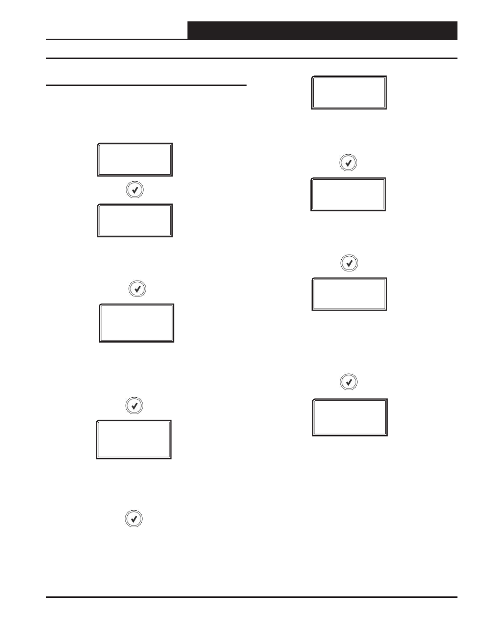
Refer to the following map when navigating through the Confi guration
Screens. From the CONFIG Screen, press
<ENTER> to scroll through
the screens and change setpoints. Use the
<UP> and <DOWN> arrow
keys to change your selections. Press
<ENTER> to save any changes.
CONFIG
ADDRESS
1 TO 4
VALVE B
ENABLED/
DISABLED
VLVSTEPS
1596,2500,
3193,6386
MAX VLV%
0 TO 100
MIN VLV%
0 TO 100
SP-A CAL
-10 TO 10
MAXIMUM VALVE POSITION
The maximum position each valve will modulate (%).
Default =100
MINIMUM VALVE POSITION
The maximum position each valve will modulate (%).
Default = 0
SUCTION PRESSURE VALVE A
CALIBRATION OFFSET
If the Suction Pressure Sensor is reading incorrectly,
you can use this offset to adjust its reading.
Default = 0
SP-B CAL
-10 TO 10
SUCTION PRESSURE VALVE B
CALIBRATION OFFSET
If the Suction Pressure Sensor is reading incorrectly,
you can use this offset to adjust its reading.
Default = 0
VALVE STEPS
Confi gurable for what valve is being used
(1596, 2500, 3193, 6386)
Default = 2500
CURRENT ADDRESS OF THE BOARD
The address confi guration is not used in Stand
Alone Mode. Stand Alone Mode Default is 1.
VALVE B ENABLED/DISABLED
When using the module for only one valve, valve
B can be disabled so false information is not dis-
played such as alarms and sensor readings.