Dual electronic expansion valve module, Installation & wiring, Technical guide – Orion System Dual Electronic Expansion Valve Module User Manual
Page 7: Important wiring considerations
Technical Guide
Dual Electronic Expansion Valve Module
7
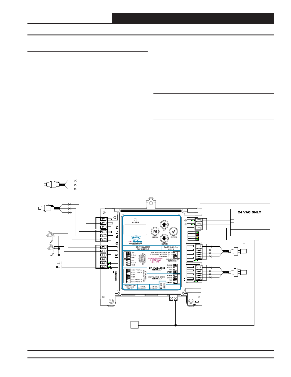
Figure 3: OE377-26-00057 Dual Electrical Expansion Valve Module Wiring Diagram
Important Wiring Considerations
Please read carefully and apply the following information when wiring
the
Dual Electronic Expansion Valve Module
Controller:
1. The Dual Electronic Expansion Valve Module requires a 24
VAC power connection with an appropriate VA rating.
2. Each Pressure Transducer must have its own 18-gauge
shielded twisted pair cable. The Drain Wire must be the “Gnd”
signal for the transducer.
3. All 24 VAC wiring must be connected so that all ground wires
remain common. Failure to follow this procedure can result in
damage to the module and connected devices.
Installation & Wiring
4. All wiring is to be in accordance with local and
national electrical codes and specifi cations.
5. Check all wiring leads at the terminal block for tightness.
Be sure that wire strands do not stick out and touch adjacent
terminals. Confi rm that all transducers required for your
system are mounted in the appropriate location and wired into
the correct terminals.
WARNING: Observe polarity! All boards must be wired
GND-to-GND and 24 VAC-to-VAC. Failure to
observe polarity could result in damage to the
boards.
GND
SERIAL #
DRIVING
BLACK
WHITE
RED
GREEN
SIG A
SIG B
+5V
+5V
GND
GND
VALVEA
VALVEB
COILTEMP A
COILTEMP B
GND
GND
D8
D7
D6
D5
C2
14
D1
D3
J1
R41
TB2
TB3
TB4
TB6
C31
MADE IN USA
YS102468 REV 3
RLYB
RLYA
COMMON
STATUS
ALARM
COMM
POWER
VALVE A DRIVE
DRIVING
BLACK
WHITE
RED
GREEN
TB1
TB7
.1
uF
VALVE B DRIVE
WATTMASTER CONTROLS
.1uF
GND
SERIAL #
DRIVING
BLACK
WHITE
RED
GREEN
SIG A
SIG B
+5V
+5V
GND
GND
VALVEA
VALVEB
COILTEMP A
COILTEMP B
GND
GND
D8
D7
D6
D5
C2
14
D1
D3
J1
R41
TB2
TB3
TB4
TB6
C31
MADE IN USA
YS102468 REV 3
RLYB
RLYA
COMMON
STATUS
ALARM
COMM
POWER
VALVE A DRIVE
DRIVING
BLACK
WHITE
RED
GREEN
TB1
TB7
.1
uF
VALVE B DRIVE
WATTMASTER CONTROLS
.1uF
COIL B - SUCTION
PRESSURE TRANSDUCER
BK
RD
WH
OE377-26-00057
Dual Electronic Expansion Valve
Module
COIL A - SUCTION
PRESSURE TRANSDUCER
BK
RD
WH
Expansion Valve A
Expansion Valve B
VALVE B ALARM ENABLE
VALVE A ALARM ENABLE
RLYA
RLYB
COMM
HVAC UNIT CONNECTIONS
R
24 V
A
C
GND
NOTE:
NORMALLY
OPEN AND RATED FOR 24 VAC POWER ONLY
ALL RELAY OUTPUTS ARE
- 1 AMP MAXIMUM LOAD
RD
WH
BK
GRN
RD
WH
BK
GRN
EXPANSION VALVE A
EXPANSION VALVE B
COIL TEMP A
SENSOR
COIL TEMP B
SENSOR