Dual electronic expansion valve module, Troubleshooting, Technical guide – Orion System Dual Electronic Expansion Valve Module User Manual
Page 21: Coil temperature sensor testing
Technical Guide
Dual Electronic Expansion Valve Module
21
Troubleshooting
Thermistor Sensor Testing Instructions
Use the resistance column to check the thermistor sensor while discon-
nected from the controllers (not powered).
Use the voltage column to check sensors while connected to powered
controllers. Read voltage with meter set on DC volts. Place the “-”
(minus) lead on GND terminal and the “+” (plus) lead on the sensor
input terminal being investigated.
If the voltage is above 4.88 VDC, then the sensor or wiring is “open.” If
the voltage is less than 0.05 VDC, then the sensor or wiring is shorted.
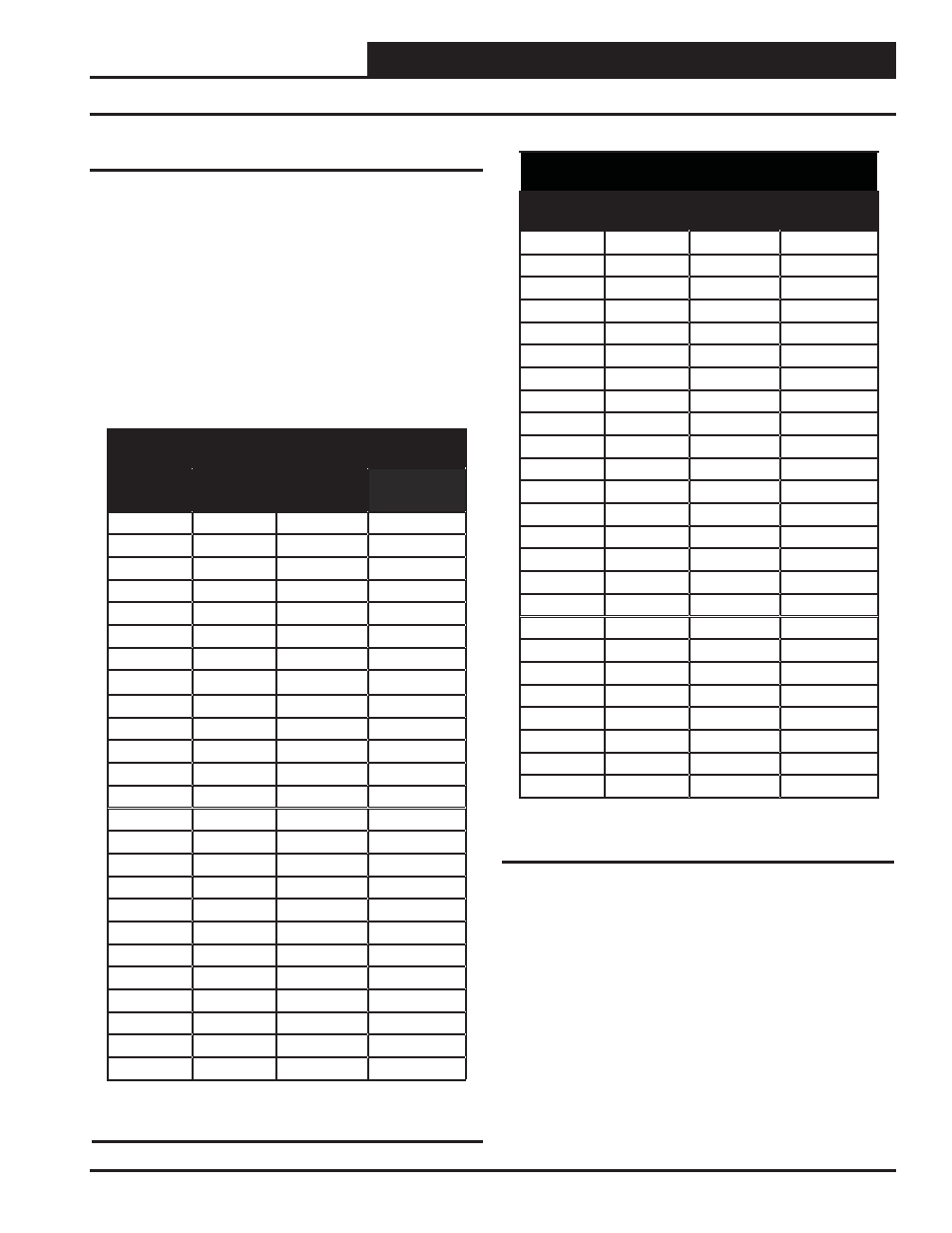
Coil Temperature Sensor Testing
The following sensor voltage and resistance table is provided to aid in
checking a coil temperature sensor that appears to be operating incor-
rectly. Many system operating problems can be traced to incorrect sensor
wiring. Be sure the sensor is wired per the wiring diagrams in this manual.
The Suction Pressure and Calculated Temperature is displayed in the
Module’s Status Screens. A voltage measurement can also be taken on
input for verifi cation.
If the sensors still do not appear to be operating or reading correctly,
check voltage and/or resistance to confi rm that the sensor is operating
correctly per the tables. Please follow the notes and instructions that
appear after the chart when checking sensors.
Temperature – Resistance – Voltage for Type III
10 K Ohm Thermistor Sensors
Temp
(ºF)
Temp
(ºC)
Resistance
(Ohms)
Voltage @
Input (VDC)
-10
-23.33
93333
4.51
-5
-20.55
80531
4.45
0
-17.77
69822
4.37
5
-15
60552
4.29
10
-12.22
52500
4.2
15
-9.44
45902
4.1
20
-6.66
40147
4.002
25
-3.88
35165
3.891
30
-1.11
30805
3.773
35
1.66
27140
3.651
40
4.44
23874
3.522
45
7.22
21094
3.39
50
10
18655
3.252
52
11.11
17799
3.199
54
12.22
16956
3.143
56
13.33
16164
3.087
58
14.44
15385
3.029
60
15.55
14681
2.972
62
16.66
14014
2.916
64
17.77
13382
2.861
66
18.88
12758
2.802
68
20
12191
2.746
69
20.55
11906
2.717
70
21.11
11652
2.691
71
21.66
11379
2.661
Temperature – Resistance – Voltage for Type III
10 K Ohm Thermistor Sensors
Temp
(ºF)
Temp
(ºC)
Resistance
(Ohms)
Voltage @
Input (VDC)
72
22.22
11136
2.635
73
22.77
10878
2.605
74
23.33
10625
2.576
75
23.88
10398
2.549
76
24.44
10158
2.52
77
25
10000
2.5
78
25.55
9711
2.464
80
26.66
9302
2.41
82
27.77
8893
2.354
84
28.88
8514
2.3
86
30
8153
2.246
88
31.11
7805
2.192
90
32.22
7472
2.139
95
35
6716
2.009
100
37.77
6047
1.884
105
40.55
5453
1.765
110
43.33
4923
1.65
115
46.11
4449
1.54
120
48.88
4030
1.436
125
51.66
3656
1.339
130
54.44
3317
1.246
135
57.22
3015
1.159
140
60
2743
1.077
145
62.77
2502
1.001
150
65.55
2288
0.931
Table 5, cont.: Temperature/Resistance for Type III
10K Ohm Thermistor Sensors
Table 5: Temperature/Resistance for Type III 10K
Ohm Thermistor Sensors