Dual electronic expansion valve module, Dimensions and mounting, Technical guide 6 – Orion System Dual Electronic Expansion Valve Module User Manual
Page 6: Power supply, Environmental requirements, Mounting
Dual Electronic Expansion Valve Module
Technical Guide
6
Dimensions and Mounting
It is important to keep the module in a location that is free from extreme
high or low temperatures, moisture, dust, and dirt. Be careful not to
damage the electronic components.
Power Supply
The
Dual Electronic Expansion Valve Module
requires a 24 VAC power
connection with a minimum power rating of 1 VA.
WARNING: Observe polarity! All boards must be wired
GND-to-GND and 24 VAC-to-VAC. Failure to
observe polarity could result in damage to the
boards.
Environmental Requirements
The
Dual Electronic Expansion Valve Module
needs to be installed in
an environment that can maintain a temperature range between -30°F
and 150°F and not exceed 90% RH levels (non-condensing).
Mounting
The
Dual Electronic Expansion Valve Module
is housed in a plastic
enclosure. It is designed to be mounted by using the 3 mounting holes
in the enclosure base. It is important to mount the module in a location
that is free from extreme high or low temperatures, moisture, dust, and
dirt. Be careful not to damage the electronic components when mount-
ing the module.
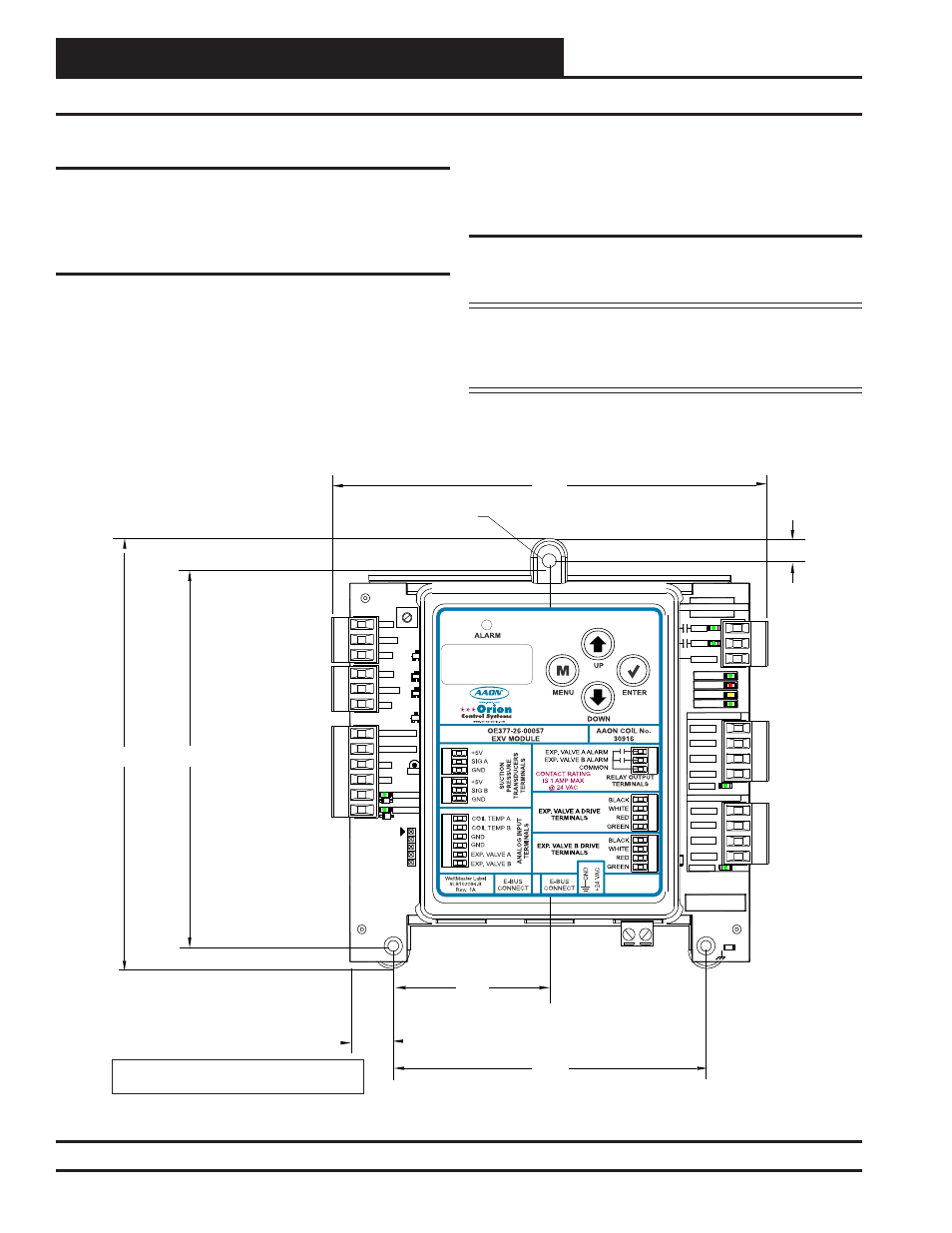
See Figure 2 for Module dimensions (in inches).
5.04
5.64
5.71
2.07
0.55
4.14
0.29
0.18 DIA. TYP.
Note: Height is 1.49 inches.
GND
SERIAL #
DRIVING
BLACK
WHITE
RED
GREEN
SIG A
SIG B
+5V
+5V
GND
GND
VALVEA
VALVEB
COILTEMP A
COILTEMP B
GND
GND
D8
D7
D6
D5
C2
14
D1
D3
J1
R41
TB2
TB3
TB4
TB6
C31
MADE IN USA
YS102468 REV 3
RLYB
RLYA
COMMON
STATUS
ALARM
COMM
POWER
VALVE A DRIVE
DRIVING
BLACK
WHITE
RED
GREEN
TB1
TB7
.1
uF
VALVE B DRIVE
WATTMASTER CONTROLS
.1uF
GND
SERIAL #
DRIVING
BLACK
WHITE
RED
GREEN
SIG A
SIG B
+5V
+5V
GND
GND
VALVEA
VALVEB
COILTEMP A
COILTEMP B
GND
GND
D8
D7
D6
D5
C2
14
D1
D3
J1
R41
TB2
TB3
TB4
TB6
C31
MADE IN USA
YS102468 REV 3
RLYB
RLYA
COMMON
STATUS
ALARM
COMM
POWER
VALVE A DRIVE
DRIVING
BLACK
WHITE
RED
GREEN
TB1
TB7
.1
uF
VALVE B DRIVE
WATTMASTER CONTROLS
.1uF
Figure 2: OE377-26-00057 Dual Electronic Expansion Valve Module Dimensions