Wshp-x module, Start-up & commissioning, Technical guide 16 – Orion System Water Source Heat Pump X Module User Manual
Page 16: General
WSHP-X Module
Technical Guide
16
Start-Up & Commissioning
General
In order to have a trouble free start-up, it is important to follow a few
simple procedures. Before applying power for the fi rst time, it is very
important to run through a few simple checks.
One of the most important checks to make before powering up the
system for the fi rst time is to make sure that the VCM-X WSHP Series
Controller or SA Series Controller is confi gured properly for your ap-
plication. Refer to the VCM-X Controller Technical Guide, VCM-X
Modular E-BUS Controller Technical Guide, SA Controller Technical
Guide, or SA E-BUS Controller Technical Guide for more information.
A handheld Modular Service Tool, Modular System Manager, or System
Manager Touch Screen connected to the VCM-X WSHP Series Control-
ler or SA Series Controller will allow you to confi gure your application.
Refer to the VCM-X Operator’s Interfaces Technical Guide, SA Operator
Interfaces Technical Guide, or System Manager TS Technical Guide for
more information.
NOTE: The SA Series Controller does not utilize the System
Manager Touch Screen.
Check all wiring leads at the terminal block for tightness. Be sure that
wire strands do not stick out and touch adjacent terminals. Confi rm
that all sensors required for your system are mounted in the appropriate
location and wired into the correct terminals.
WARNING: Observe polarity! All boards must be wired
GND-to-GND and 24 VAC-to-VAC. Failure to
observe polarity could result in damage to the
boards.
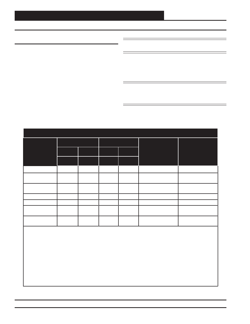
Table 1: Unit Confi gurations Chart
UNIT CONFIGURATIONS
PERMUTATION
SYSTEM A
SYSTEM B
VCM-X WSHP
CONFIGURATION
SA
CONFIGURATION
Comp A1
Comp A2 Comp B1 Comp B2
Relay 1
Relay 2
Relay 3
Relay 4
1
On/Off
On/Off
—
—
2 Compressors
—
2
Digital
On/Off
—
—
2 Compressors
Digital Compressor
2 Compressors
Single Unit SA
3
Digital
Digital
—
—
2 Compressors
Full Digital
2 Compressors
Single Unit SA
4
On/Off
On/Off
On/Off
On/Off
4 Compressors
—
5
Digital
On/Off
On/Off
On/Off
Not Available
—
6
Digital
On/Off
Digital
On/Off
4 Compressors
Digital Compressor
4 Compressors
Dual Unit SA
7
Digital
Digital
Digital
Digital
4 Compressors
Full Digital
4 Compressors
Dual Unit SA
In the Cooling Mode, the Compressors will stage in the following order:
Permutations 1, 2 & 3: Compressor A1 -> Compressor A2
Permutations 4: Compressor A1 -> Compressor B1 -> Compressor A2 -> Compressor B2
Permutations 6: Compressor A1 & Compressor B1 -> Compressor A2 -> Compressor B2
Permutations 7: Compressor A1 & Compressor B1 -> Compressor A2 & Compressor B2
In the Dehumidifi cation Mode, the Compressors will stage in the following order:
Permutation 4: Compressor A1 & Compressor B1 -> Compressor A2 -> Compressor B2
All other permutations in the Dehumidifi cation Mode stage as described in the Cooling Mode.