Wshp-x module, Sequence of operation, Technical guide – Orion System Water Source Heat Pump X Module User Manual
Page 17: General, Wshp-x module setpoints
Technical Guide
WSHP-X Module
17
Sequence of Operation
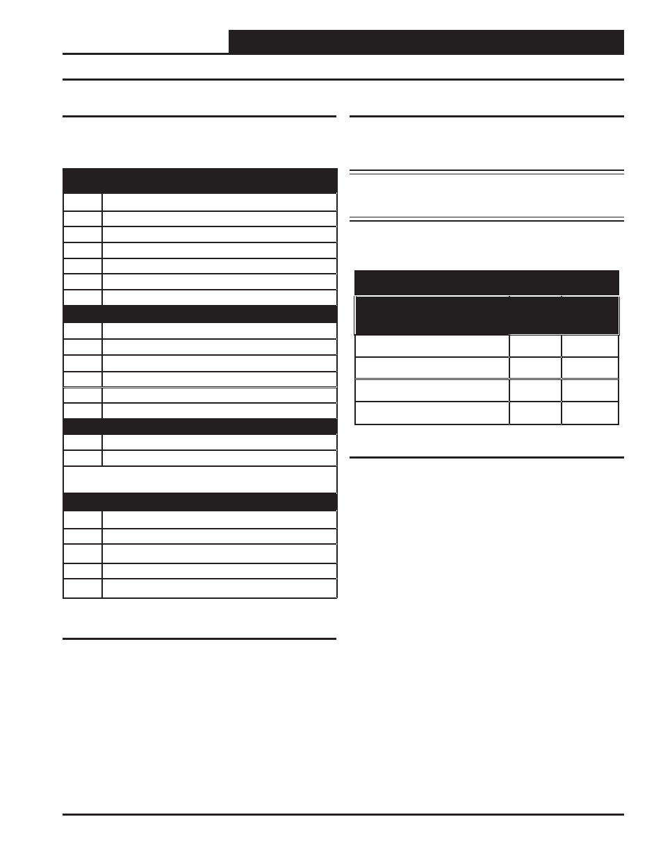
Table 2: WSHP-X Module Inputs & Outputs
General
The following inputs and outputs are available on the WSHP-X Module.
See Table 2 below to reference the Input/Output Map.
WSHP-X Module Setpoints
The WSHP-X Module setpoints are preset at AAON and are based on
the unit’s design as well as the type of coolant being used in the water
loop. See Tables 3 & 4 for default settings.
NOTE: These are default settings only. The setpoints may be
different based on the unit’s design and coolant being
used.
Binary Inputs
1
Compressor A1 Enable (BIN 1)
2
Compressor A2 Enable (BIN 2)
3
Compressor B1 Enable (BIN 3)
4
Compressor B2 Enable (BIN 4)
5
Heat Enable (BIN 5)
6
Water Proof of Flow System A (BIN 6)
7
Water Proof of Flow System B (BIN 7)
Analog Inputs
1
Suction Pressure A1 (Pres 1)
2
Suction Pressure A2 (Pres 2)
3
Suction Pressure B1 (Pres 3)
4
Suction Pressure B2 (Pres 4)
5
Leaving Water Temperature System A (T1)
6
Leaving Water Temperature System B (T2)
Analog Outputs (1-5 VDC or 0-10 VDC)
1
Digital Stage 1 (Compressors A1 & B1) (AOUT1)
2
Digital Stage 2 (Compressors A2 & B2) (AOUT2)
NOTE: Analog Outputs are not used on Stand
Alone Application
Relay Outputs (24 VAC)
1
Compressor A1 Enable Output (RLY1)
2
Compressor A2 Enable Output (RLY2)
3
Compressor B1 Enable Output (RLY3)
4
Compressor B2 Enable Output (RLY4)
5
Alarm Output (RLY5)
Table 3: Factory-Set Default Setpoints - Water Only
Water-Only Default Setpoints
Description
R410-A
R22
UNSAFE SUCTION
40 PSIG
20 PSIG
LOW SUCTION HEAT MODE
100 PSIG
57 PSIG
LOW SUCTION COOL MODE
85 PSIG
57 PSIG
LOW LEAVING WATER TEMP
37ºF
37ºF