Auxiliary i/o connection – Research Concepts RC2500 User Manual
Page 134
RC2500 Antenna Controller
Appendix L
Replacing the Electrospace 93C-23 127
Research Concepts, Inc. • 5420 Martindale Road • Shawnee, Kansas 66218-9680 • USA
www.researchconcepts.com
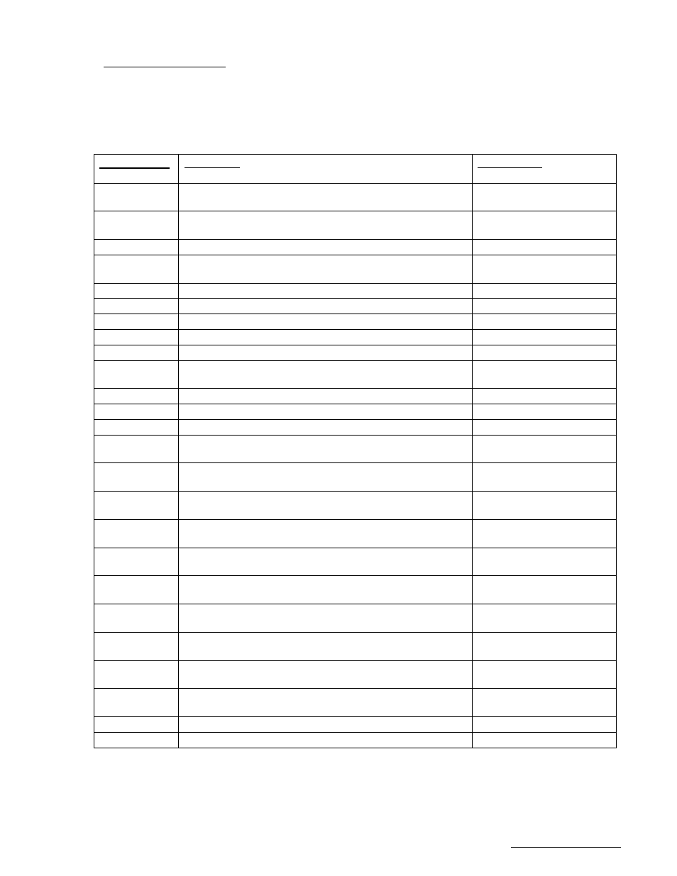
Auxiliary I/O Connection
J6, located directly above J7, is the Auxiliary I/O connector. This port, based on a DB-25 receptacle,
supports isolated, axis-specific limit inputs as well as contact closures for summary faults and peripheral
equipment control. A +5 VDC regulated output (200mA max), a +24 VDC unregulated output (1 Amp
max), and an analog voltage input, all referenced to the RC2500 ground, are also available The individual
pin definitions are shown in the table below. Both J6 and J7 are required when operating with the
Electrospace 83MC4 A.I.U. that support separate limits.
RC2500 Pin #
& (resource)
Description
83MC4 Pin #
1 (PC3)
Summary Fault dry contact COM, (3A @ 125VAC or 3A
@ 30VDC).
Unused
2 (PC3)
Summary Fault dry contact NO, (3A @ 125VAC or 3A @
30VDC).
Unused
3 (PB1)
Drive Ground (Azimuth CW Limit return).
DRIVE GND TB3-1,2
4 (PB0,
HSI.1, P2.4)
Drive Ground (Interlock Status and Az CCW Lim return;
same as J7-17)
DRIVE GND TB3-1,2
5 (PB2)
Drive Ground (Elevation Down Limit return.)
DRIVE GND TB3-1,2
6 (PB3)
Drive Ground (Elevation Up Limit return)
DRIVE GND TB3-1,2
7 (PB5)
Drive Ground (Polarization CW Limit return).
DRIVE GND TB3-1,2
8 (PB4)
Drive Ground (Polarization CCW Limit return).
DRIVE GND TB3-1,2
9
Drive Common (return path, same as J6, pins 2,5,8)
DRIVE GND TB3-1,2
10 (PC0)
PC0 output dry contact NC, (3A @ 125VAC or 3A @
30VDC).
Unused
11 (P0.2)
P0.2 Auxiliary analog/digital input 0 - +5 VDC.
Unused
12
Ground (for digital/analog I/O).
Unused
13
Ground for system bus voltages.
Unused
14 (PC3)
Summary Fault dry contact NC, (3A @ 125VAC or 3A @
30VDC).
Unused
15 (PB1)
Azimuth CW Limit input, 24 VDC low current. (0V = CW
Limit reached)
AZ CW Limit Status
TB3-19
16 (PB0)
Azimuth CCW Limit input, 24VDC (0V = CCW Limit
reached) (same as J7-10 ).
AZ CCW Limit Status
TB3-18
17 (PB2)
Elevation Down Limit input, 24 VDC low current. (0V =
Down Limit reached)
EL Down Limit Status
TB3-21
18 (PB3)
Elevation UP Limit input, 24 VDC low current. (0V = Up
Limit reached)
EL Up Limit Status
TB3-22
19 (PB5)
Polarization CW Limit input, 24 VDC low current. (0V =
CW Limit reached)
POL CW Limit Status
TB3-??
20 (PB4)
Polarization CCW Limit input, 24 VDC low current. (0V =
CCW Limit reached)
POL CCW Limit Status
TB3-??
21 (PC1)
Polarization Direction, pull-down drive, 700mA max sink.
(0.4V = move CCW)
POL CW/CCW TB3-??
22 (PC0)
PC0 output dry contact COM, (3A @ 125VAC or 3A @
30VDC).
unused
23 (PC0)
PC0 output dry contact NO, (3A @ 125VAC or 3A @
30VDC).
unused
24
+5 Volts DC digital power, 200mA max.
unused
25
Unregulated +24 VDC bus voltage, 1 Amp max..
unused