Auxiliary input connection, j4 – Research Concepts RC2500 User Manual
Page 159
152
RC2500 Antenna Controller
Appendix S
Andrew Plug Compatible Controller
Research Concepts, Inc. • 5420 Martindale Road • Shawnee, Kansas • 66218-9680 • USA
www.researchconcepts.com
Auxiliary Input Connection, J4
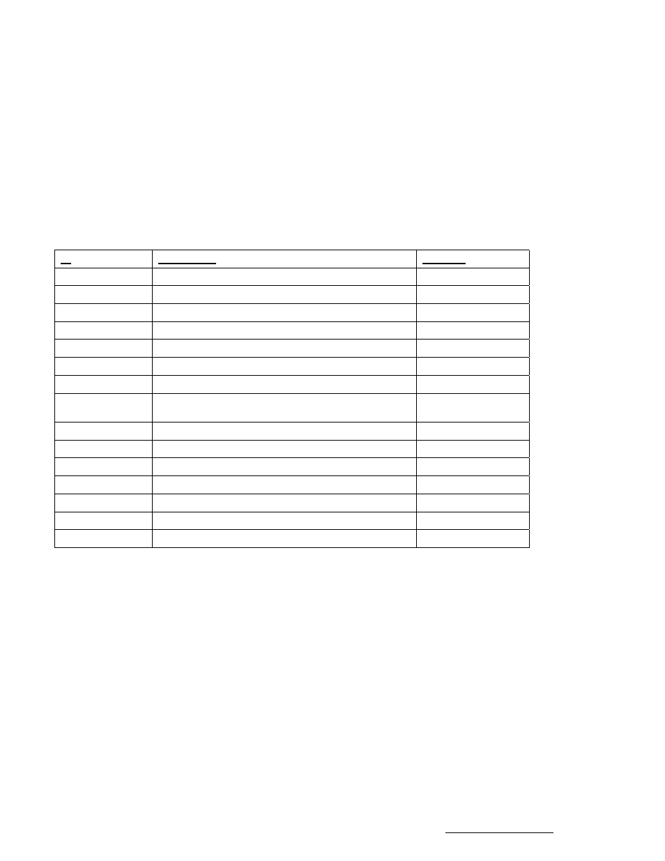
J4, located next to the MOTOR CONTROL Connector on the back panel, is a DB-15R connector
identified as the AUX. INPUT connector. This connector acts as a “Hard” limit switch input port for the
RC2500 ANDREW. Hard Limits are NOT supported in the current RC2500-ANDREW firmware version.
The port includes 6 limit switch inputs, 2 inverter fault inputs and a hand held remote control sensor
input. The individual pin definitions are shown in the table below. Andrew ACUs use “Soft” limits rather
than “Hard” limits. For additional information on these inputs examine Figure S-2, “RC2500 – ANDREW
BLOCK DIAGRAM, BASIC LIMIT SWITCH CIRCUITRY Sheet 1”.
J4 Pin #(resource
)
Description
APC300 Pin #
1
LIMIT COM (Common for Limits)
No Equivalent
2 (HSI.1)
EL INV FAULT -
No Equivalent
3 (PB6 C)
HH REM SENSE - (Hand Held Remote Sense C)
No Equivalent
4 (PB1 C)
AZ CW LIMIT -
No Equivalent
5 (PB3 C)
EL UP LIMIT -
No Equivalent
6 (PB5 C)
POL CW LIMIT -
No Equivalent
7
No Connection
8
LIMIT SRC (Not normally used, see note) No Equivalent
9 (P2.4 C)
AZ INV FAULT -
No Equivalent
10
INV FAULT COM
No Equivalent
11 (PB6 A)
HH REM SENSE + (Hand Held Remote Sense A)
No Equivalent
12 (PB0 C)
AZ CCW LIMIT -
No Equivalent
13 (PB2 C)
EL DOWN LIMIT -
No Equivalent
14 (PB4 C)
POL CCW LIM -
No Equivalent
15
No Connection
Note: Pin 8 (LIM SRC) is not normally used. This is the isolated supply that powers the limit sensing
circuitry. An External Positive voltage of 5 to 12 Volts may be connected here, however R13 must be
removed from the PC Board first. The Negative terminal of this supply is Pin (LIM COM).