Rear connectors, Power connection, Usb connector – Ensemble Designs BrightEye 72 SDI to HDMI Converter, Color Corrector and Broadcast Confidence Monitor User Manual
Page 13: Hdmi out, Audio out
www.ensembledesigns.com
BrightEye 72 and 72-F - Page 13
3G/HD/SD SDI to HDMI Converter User Guide
TM
BrightEye 72 and 72-F
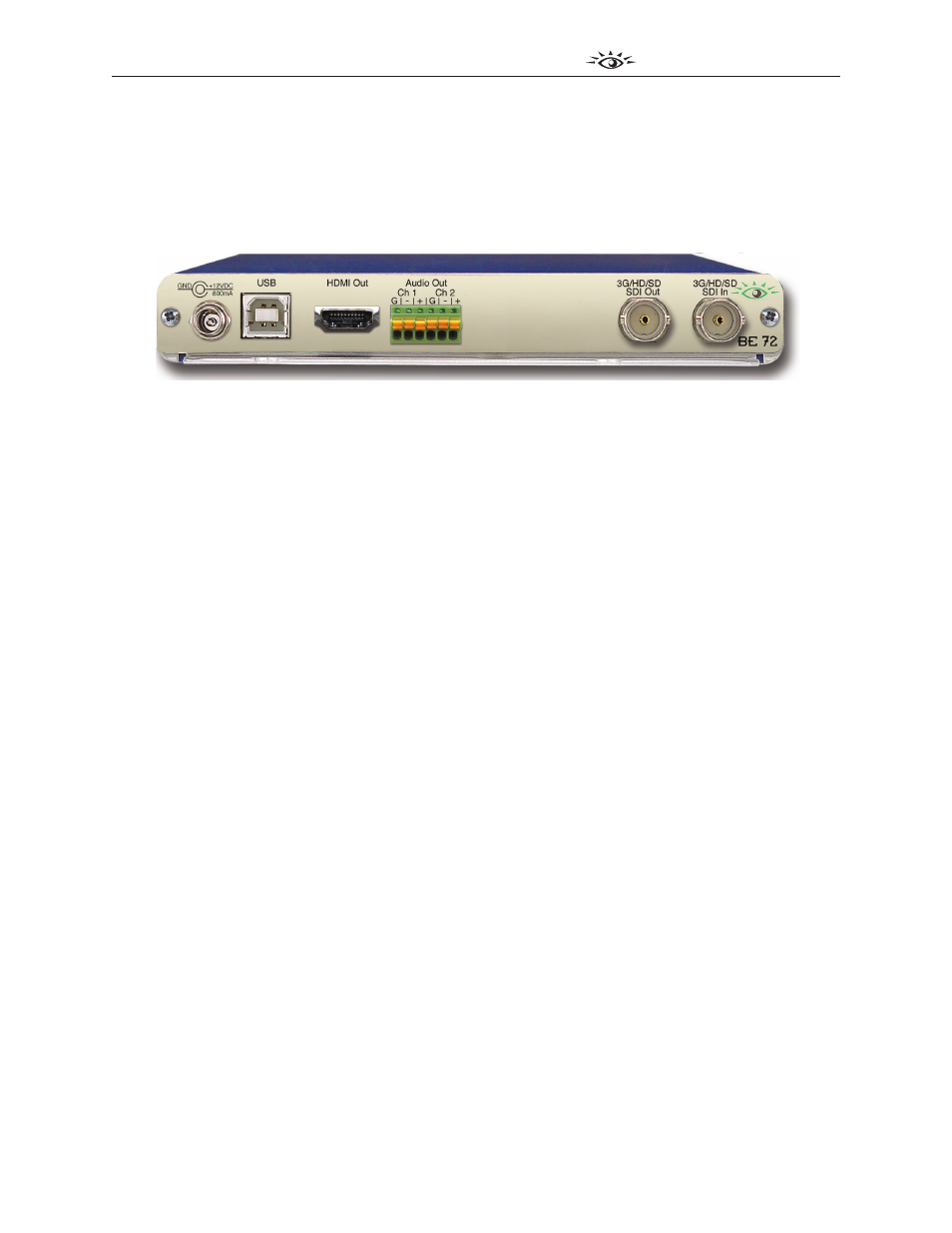
Rear Connectors
All connections to the BrightEye 72/72-F are made on the rear of the unit. Refer to the illustration
below as a reference for the rear connectors. A more detailed explanation of the rear connectors
follows immediately below.
Power Connection
Connect the modular power supply to the 12-volt DC power input connection on the far left of the
unit. Use the locking ring to secure it. If you don’t have a power supply, contact Ensemble Designs to
purchase one.
USB Connector
Connect the USB port to a PC or Mac running BrightEye software for more comprehensive control,
diagnostics, and upgrades to the unit. The BrightEye PC/Mac Control software is included on the CD
that came with your unit. You can also download the software from this URL:
http://www.ensembledesigns.com/support/brighteye-support/
HDMI Out
The High Definition Multimedia Interface (HDMI) is an uncompressed, all-digital interface that
transmits digital video and eight channels of digital audio. The mapping of the first 8 channels of
audio on the incoming SDI signal will pass through the HDMI output. HDMI is a bit-serial interface that
carries the video content in digital component form over multiple twisted-pairs. The HDMI interface
standard supports limited cable length as compared to SD and HD SDI. The use of cables over 10m (30
feet) is not recommended. Connect the HDMI output to your video monitor.
Audio Out
The Audio Out connector provides two channels of balanced analog audio. This connector is fitted
with a pluggable terminal block that accepts bare wire leads. Wires can be inserted into the small
round holes. Depress the orange tab to release them.
Follow the legend to connect the Ground (G), Positive (+), and Negative (-) connections for each signal.
Ch 1 corresponds to the left channel in a stereo system, and Ch 2 corresponds to the right channel.
If connecting to an unbalanced (single-ended) destination, such as a consumer speaker amplifier, with
shielded coaxial style audio cable, connect the center conductor to the Positive (+) terminal. Then
connect the outer conductor to both the Ground (G) and Negative (-) terminals. Analog reference
levels can be configured from the BrightEye Control application.