Ntp broadcast mode configuration example, Network requirements, Configuration procedure – H3C Technologies H3C SecPath F1000-E User Manual
Page 126
115
As shown above, SecPath B has been synchronized to SecPath C, and the clock stratum level of
SecPath B is 2, while that of SecPath C is 1.
# View the NTP session information of SecPath B, which shows that an association has been set up
between SecPath B and SecPath C.
[SecPathB] display ntp-service sessions
source reference stra reach poll now offset delay disper
**************************************************************************
[245] 3.0.1.31 127.127.1.0 2 15 64 24 10535.0 19.6 14.5
[1234] 3.0.1.33 LOCL 1 14 64 27 -77.0 16.0 14.8
note: 1 source(master),2 source(peer),3 selected,4 candidate,5 configured
Total associations : 2
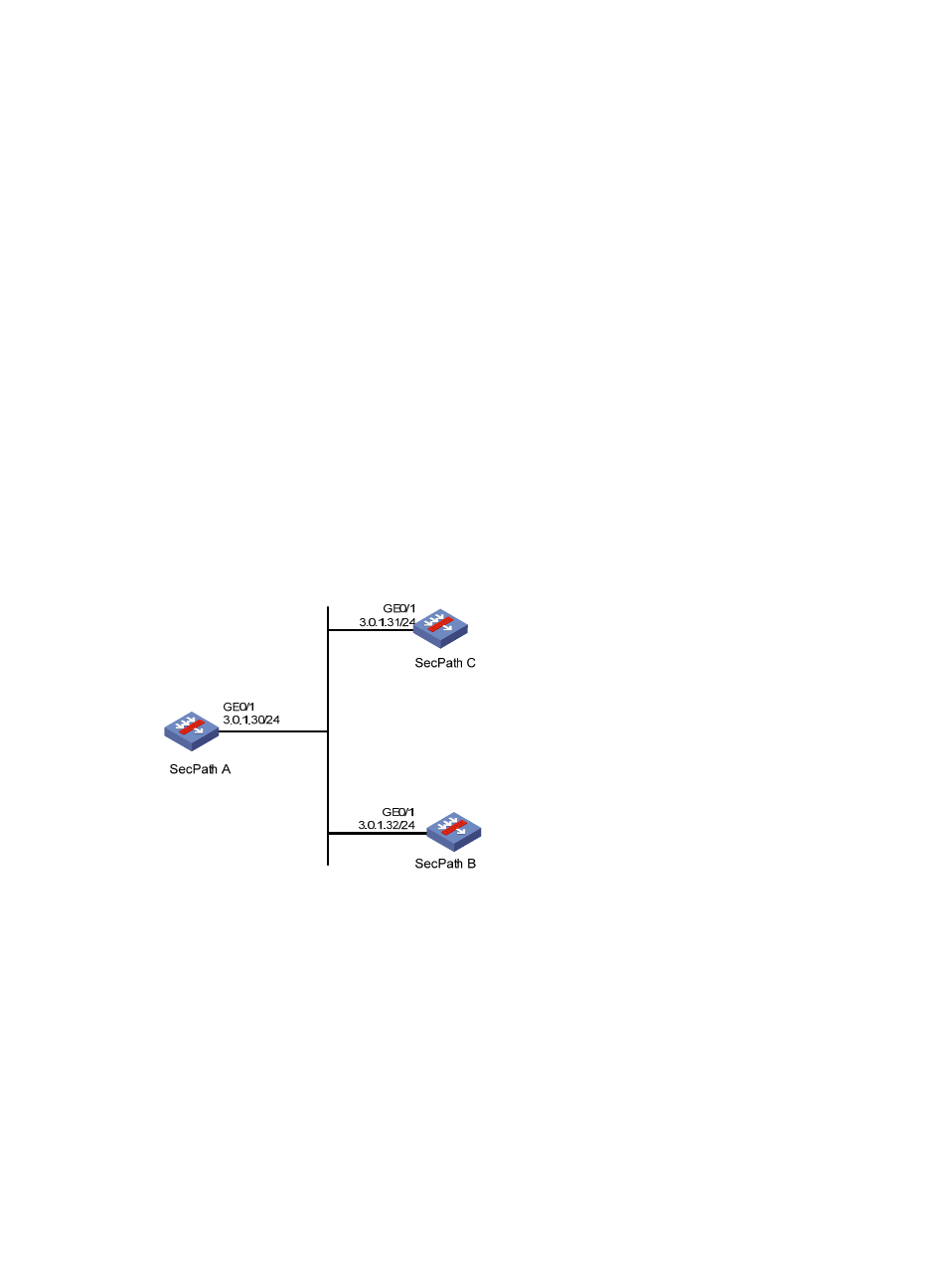
NTP broadcast mode configuration example
Network requirements
As shown in
, SecPath C functions as the NTP server for multiple devices on a network segment
and synchronizes the time among multiple devices. SecPath C’s local clock is to be used as a reference
source, with the stratum level of 2. SecPath C operates in broadcast server mode and sends out
broadcast messages from GigabitEthernet 0/1. SecPath B and SecPath A operate in the broadcast client
mode and receive broadcast messages through their respective GigabitEthernet 0/1.
Figure 52 Network diagram
Configuration procedure
1.
Set the IP address for each interface as shown in
. (Details not shown.)
2.
Configure SecPath C:
# Specify the local clock as the reference source, with the stratum level of 2.
<SecPathC> system-view
[SecPathC] ntp-service refclock-master 2
# Configure SecPath C to operate in broadcast server mode and send broadcast messages
through GigabitEthernet 0/1.
[SecPathC] interface GigabitEthernet 0/1
[SecPathC-GigabitEthernet0/1] ntp-service broadcast-server
3.
Configure SecPath A:
- H3C SecPath F5000-A5 Firewall H3C SecPath F1000-A-EI H3C SecPath F1000-E-SI H3C SecPath F1000-S-AI H3C SecPath F5000-S Firewall H3C SecPath F5000-C Firewall H3C SecPath F100-C-SI H3C SecPath F1000-C-SI H3C SecPath F100-A-SI H3C SecBlade FW Cards H3C SecBlade FW Enhanced Cards H3C SecPath U200-A U200-M U200-S H3C SecPath U200-CA U200-CM U200-CS