Configuration, Chapter – Grass Valley PDR100 User Manual
Page 17
PDR100 Installation
2-1
Chapter
2
Configuration
The PDR100 Mother board with its connectors for the circuit boards allows the
PDR100 to be configured in a number of ways. Any configuration of the PDR100
consists of circuit boards that are required in all configurations and circuit boards
specific to a particular configuration.
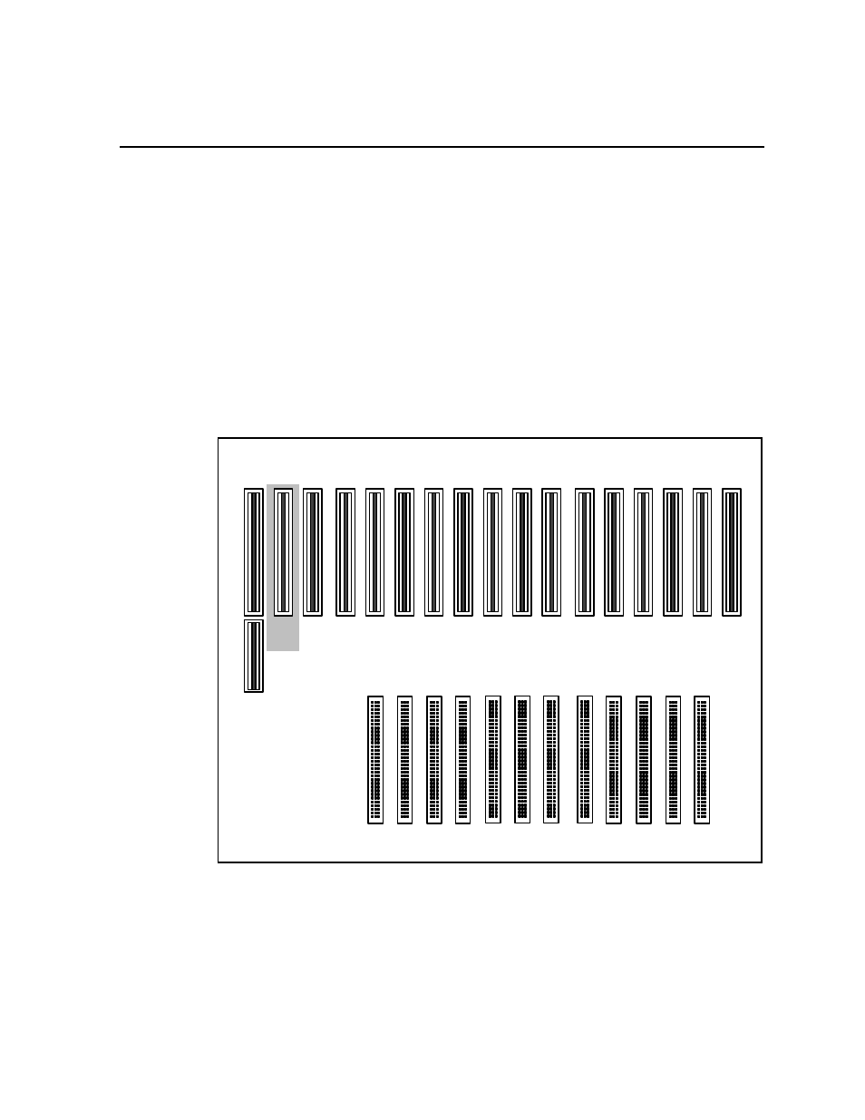
On the Mother board, the connectors are arranged into the EISA bus and Video Router
as shown in Figure 2-1. All of the circuit boards plug into the EISA bus. (Slot J2,
which is on the EISA bus, is limited to ISA only.) A number of the circuit boards, such
as the Master or Slave Disk Recorder and the Input/Output (I/O) boards, require
connection to both the EISA bus and the Video Router, which is provided by slots
J5-J16.
Figure 2-1. Circuit Board Slot Nomenclature
J1
J2
J5
J105
J17
J16
J14
J9
ISA
Only
EISA Bus
Video Router
J116
J109
J112
9040-2