Reference genlock circuit board (required slot j16 – Grass Valley PDR100 User Manual
Page 53
Reference Genlock Circuit Board (Required
PDR100 Installation
3-29
Reference Genlock Circuit Board (Required Slot J16)
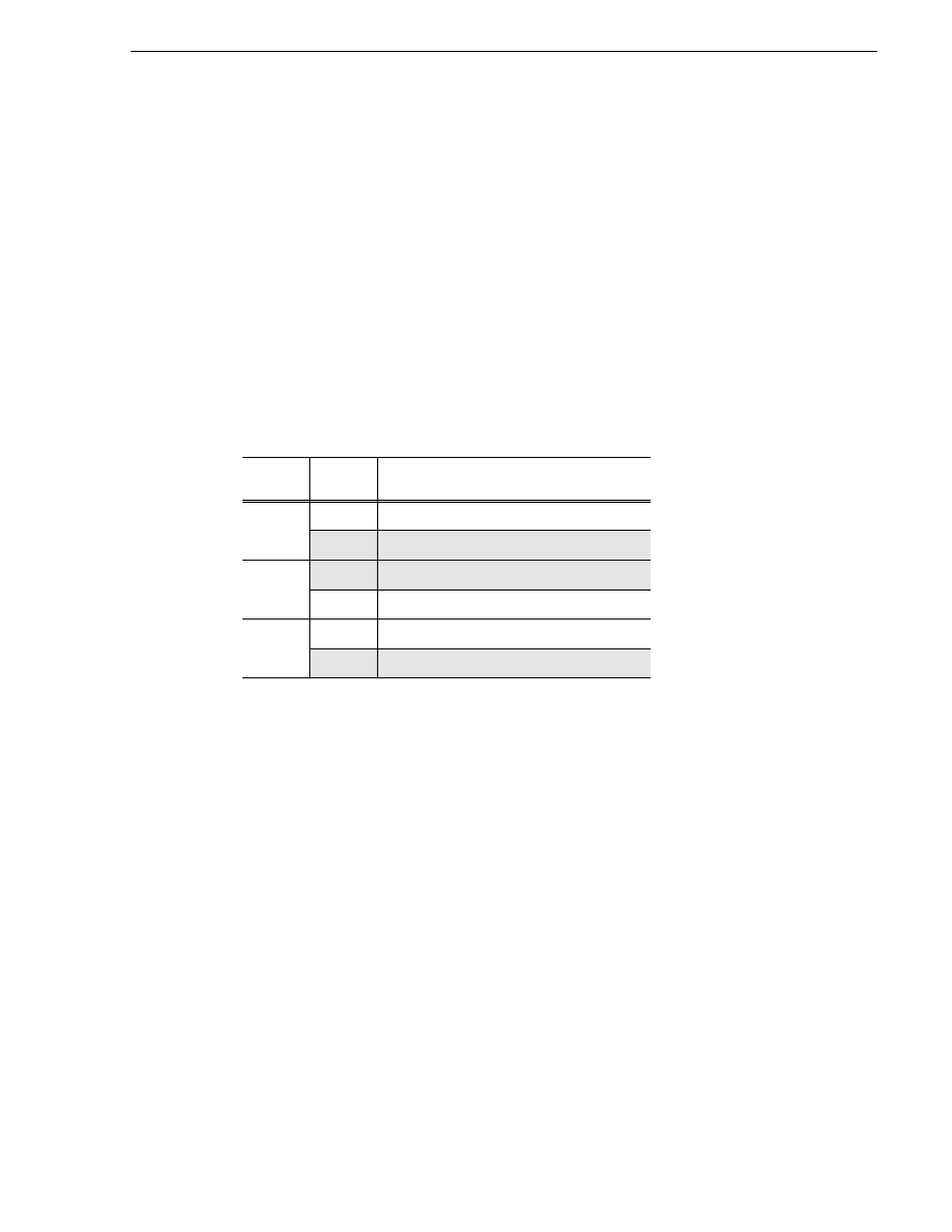
The Reference Genlock circuit board has three plug jumpers. One, J4, disables the
burst-lock loop for test purposes. J7 and J8 were used to develop a programmed part,
and should always remain in the factory-installed positions. See Table 3-11.
Factory-installed positions are marked with a ] symbol, on the circuit board. J1, J3,
J5, and J6 are connectors for the system clock (27 MHz) that can be used as additional
audio play clocks.
The Reference Genlock board also has a four-position dip switch (see the insert in
Figure 3-28) used to enable 600
Ω
termination for each of the LTC inputs (input
impedance in the “open” position is 20 k
Ω
. The four rockers on the switch are shipped
from the factory in the “open” position as marked on the switch. To enable the 600
Ω
termination for any LTC channel, shift the rocker for that channel to the enable
position. The channel number for each rocker is screened on the board (NOT on the
switch--the numbers on the switch are reversed).
Table 3-11. Reference Genlock Plug Jumper Settings
Plug
Jumper
Position
Operation
J4
1 - 2
Test Burst Phase Lock Loop Disabled
2 - 3
Normal Operation (Factory-Installed Position)
J7
1 - 2
Normal Operation (Factory-Installed Position)
2 - 3
Program Part Development
J8
1 - 2
Down Loads Over EISA Bus
2 - 3
Normal Operation (Factory-Installed Position)