Chapter 3 mechanical installation – Grass Valley PDR100 User Manual
Page 58
Chapter 3 Mechanical Installation
3-34
PDR100 Installation
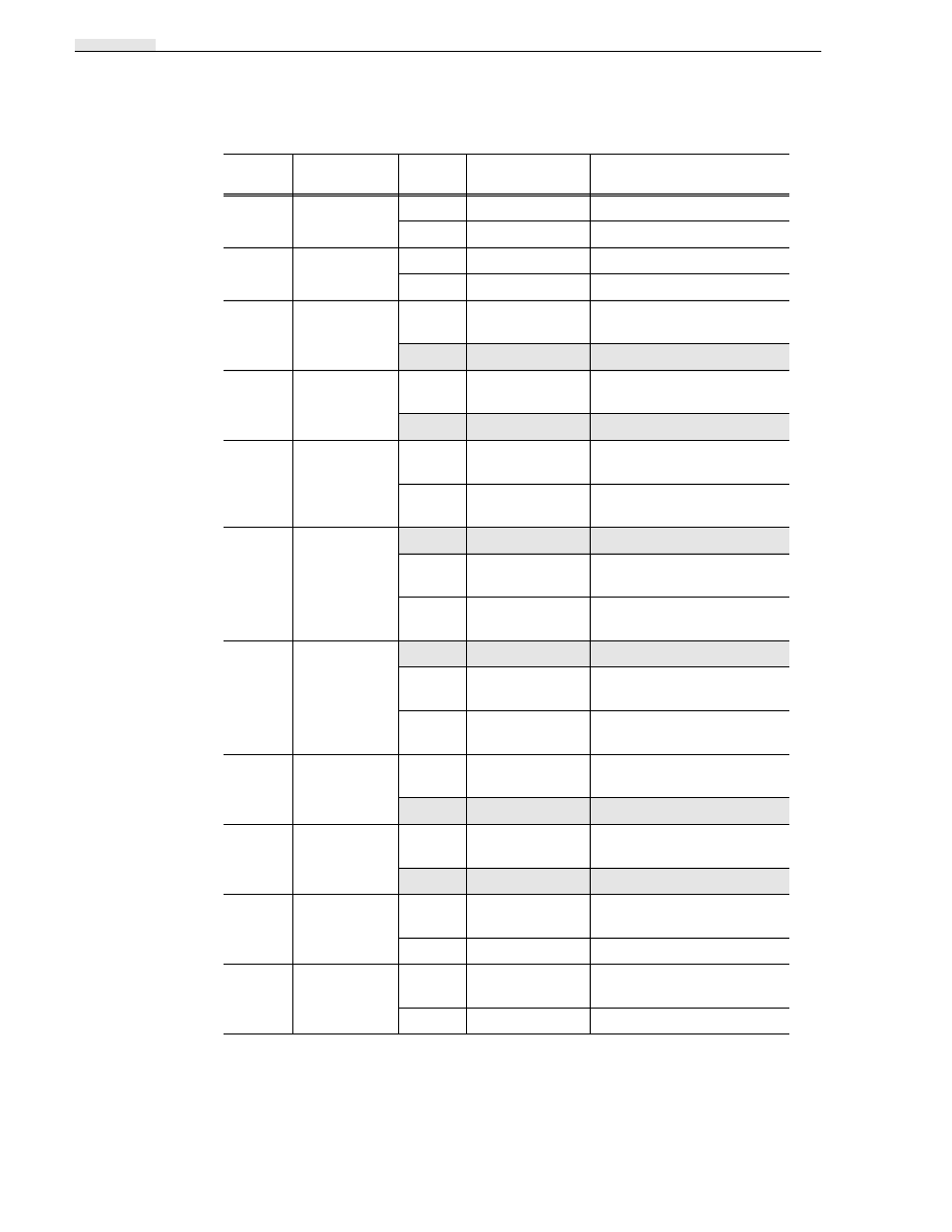
Table 3-12. Serial Digital I/O Plug Jumpers
Jumper
Name
Position
Factory-
Installed
Operation
J1
Monitor Point
Pin 1
Internal Clock 2
Pin 2
Ground
J2
Monitor Point
Pin 1
Internal Clock 1
Pin 2
Ground
J3
Serial Video
Input 1 VCO
Frequency
1-2
Test Position to set VCO free
run frequency.
2-3
2-3
Operate
J4
Serial Video
Input 2 VCO
Frequency
1-2
Test Position to set VCO free
run frequency.
2-3
2-3
Operate
J6
Audio Clock
Test Points
1-2
Open
Audio Clock 2 Test Point
Pin 1 (Clock) Pin 2 Ground
3-4
Open
Audio Clock 1 Test Point
Pin 3 (Clock) Pin 4 Ground
J8
Serial Channel
1 Video
Present
1-2
1-2
Normal Operation
2-3
Video 1 Present pulled low to
adjust VCO free run frequency
3-4
Video 1 Present pulled high
forces video clock output
J9
Serial Channel
2 Video
Present
1-2
1-2
Normal Operation
2-3
Video 2 Present pulled low to
adjust VCO free run frequency
3-4
Video 2 Present pulled high
forces video clock output
J34
Serial Video
Output 1 VCO
Frequency
1-2
Test Position to set VCO free
run frequency.
2-3
2-3
Operate
J35
Serial Video
Output 2 VCO
Frequency
1-2
Test Position to set VCO free
run frequency.
2-3
2-3
Operate
J40
Monitor Point
Pin 1
VCO Frequency for Serial
Output 2
Pin 2
Ground
J41
Monitor Point
Pin 1
VCO Frequency for Serial
Output 1
Pin 2
Ground