Serial digital i/o circuit board – Grass Valley PDR100 User Manual
Page 57
Serial Digital I/O Circuit Board
PDR100 Installation
3-33
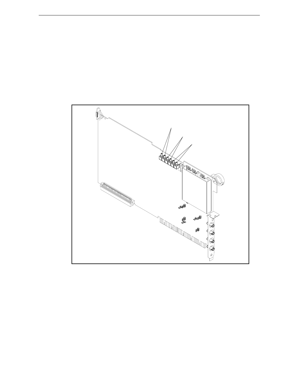
Serial Digital I/O Circuit Board
The Serial Digital I/O board is optional, and can occupy various slots from J6-J13.
The Serial Digital I/O circuit board has a number of plug jumpers in order to
accommodate a number of operating circumstances. In addition it has six connectors
that are used to route clock signals to the Audio I/O circuit boards. See Figure 3-31.
The Serial Digital I/O board with embedded audio capability does not have all the
jumpers shown in Figure 3-31. The connectors for clock signals are present on the
board, but there are no clock connections to make since there can be no Audio boards
in use at the same time as the embedded audio Serial Digital I/O board.
Figure 3-31. Serial Digital I/O Circuit Board Showing Plug Jumpers
J6
J8
J9
J2
J34
J40
J35
J41
J3
J4
J1
J23
J22
J15
J14
J13
J12
CH1
CH2
SYSTEM
CLOCK