Circuit boards that support configurations, Slave disk recorder, Analog composite input – Grass Valley PDR100 User Manual
Page 20
Chapter 2 Configuration
2-4
PDR100 Installation
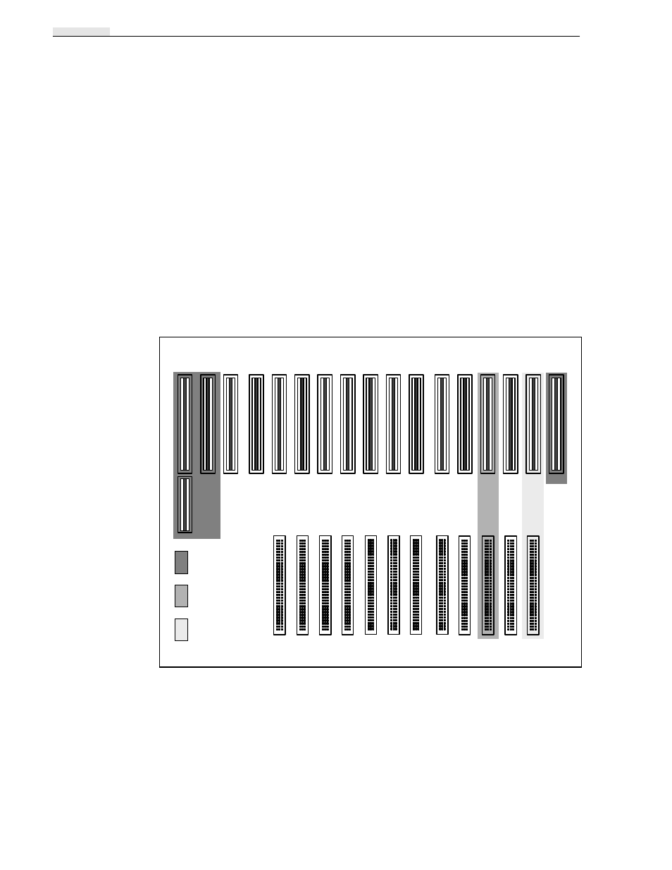
Circuit Boards that Support Configurations
Some of the circuit boards can be loaded into almost any of the slots, while others
must go into specified locations. The slots that are available for configuration-specific
circuit boards are J3 through J13. See Figure 2-2.
J14 through J17 are also dedicated slots, used for the Disk Recorders, Reference
Genlock, and RS422A Interface circuit boards.
Slave Disk Recorder
When the PDR100 is configured for four channel operation, a Slave Disk Recorder
circuit board is required. This circuit board is always located in slot J15.
Analog Composite Input
The Analog Composite Video Input is a two circuit board set requiring two EISA/
Video Router slots (between J5 and J13.) One slot is occupied by the Decoder circuit
board, while the second slot has the one video-channel Input circuit board.
Figure 2-2. Required Circuit Boards for All Configurations
J116
J1
J2
J5
J105
J17
J16
J14
J9
J109
J112
Processor,
Master Disc
Controller
Reference
Genlock
VGA, & RS-422 I/O
EISA Bus
Video Router
9040-3