Processor circuit board – Grass Valley PDR100 User Manual
Page 47
Processor Circuit Board
PDR100 Installation
3-23
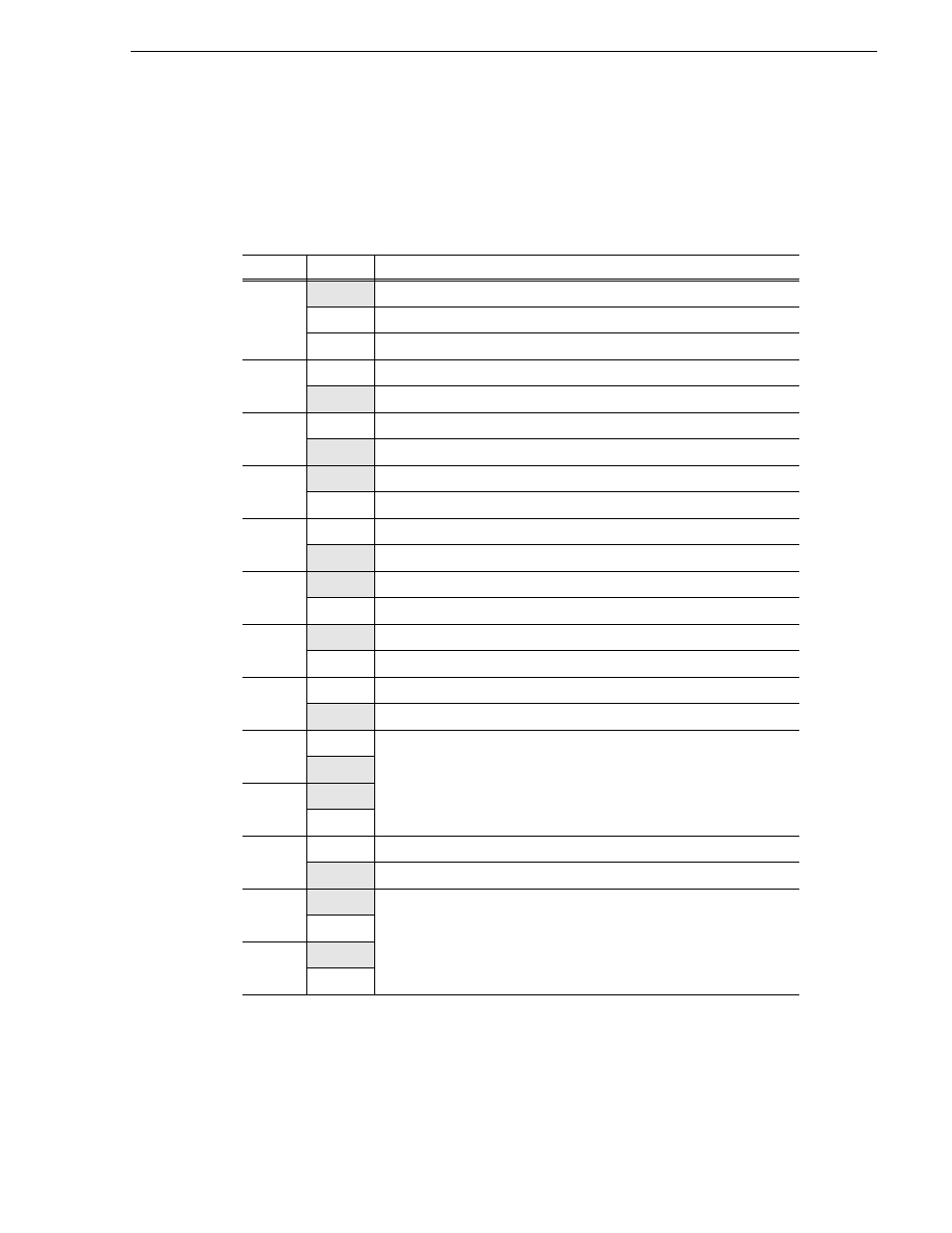
Table 3-3 lists each jumper and its function. The shaded listings are the factory
settings for the jumpers. A position of “On” or “Off” indicates whether or not the
jumper is installed. A position of “1-2” or “2-3” indicates the pins on which the
jumper is installed.
Table 3-3. Processor Board Jumper Settings
Jumper
Position
Function
E1
Off
No Interrupt
1-2
IRQ11
2-3
IRQ10
E2
On
/XT Keyboard
Off
PS/2 or /AT Keyboard
E3
On
Manufacturing Test
Off
Normal Mode
E4
On
Color Display
Off
Monochrome Display
E5
1-2
Disable BIOS 12 Volts
2-3
Enable FLASH programming
E6
On
Connect mounting bracket to CPU ground.
Off
Disconnect mounting bracket from CPU ground.
E7
On
Serial Port Mode: DTE (connect to a modem -/AT standard)
Off
Serial Port Mode: DCE (connect to a CPU)
E8
On
Dual CPU
Off
Single CPU
E9
On
Select 133MHz clock speed
Off
E10
On
E11
1-2
CPU takes priority on EISA bus.
2-3
EISA master takes priority on EISA bus - EISA bus throughput increased
E12
1-2
Select 512K Cache
2-3
E13
1-2
2-3