3 explanation of symbols, 1 symbols on the inverter, Explanation of symbols – SMA SB 3300-11 Installation User Manual
Page 12: Symbols on the inverter
Safety
SMA Solar Technology AG
12
SB33-38-11-IA-en-62
Installation Manual
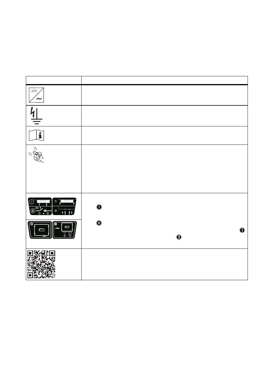
2.3 Explanation of Symbols
This section gives an explanation of all the symbols found on the inverter and on the type label.
2.3.1 Symbols on the Inverter
* This function is valid from firmware version 4.00
** optional
*** QR-Code is a registered trademark of DENSO WAVE INCORPORATED.
Symbol
Explanation
Operation display.
Indicates the operating state of the inverter.
Ground fault or varistor defective.
Read section 9.3 "Red LED is Glowing Continuously" (page 56).
Fault or disturbance.
Read section 9 "Troubleshooting" (page 50).
You can operate the display by tapping the enclosure lid:
• Tapping once: the backlight switches on or the display scrolls to the
next display message.
• Tapping twice in quick succession*: The inverter shows the display
messages from the startup phase again (see section 6.2 "Display
Messages During the Startup Phase" (page 40)).
DC switch-disconnector Electronic Solar Switch (ESS)**
•
When the Electronic Solar Switch is plugged in,
the DC electric circuit is closed.
•
In order to interrupt the DC electric circuit and disconnect the
inverter safely under load, first pull out the Electronic Solar Switch
and then remove all DC connectors as described in section
7.2 "Opening the Inverter" (page 41).
QR-Code
®
*** for SMA bonus program
You will find information on the SMA bonus program at
www.SMA-Bonus.com.
DC
2
1